GA-M61SME-S2 AMD AthlonTM 64 FX / AthlonTM 64 X2 Dual-Core / AMD AthlonTM 64 / SempronTM AM2 Processor Motherboard User's Manual Rev.
Motherboard GA-M61SME-S2 Mar. 7, 2007 Motherboard GA-M61SME-S2 Mar.
Copyright © 2007 GIGA-BYTE TECHNOLOGY CO., LTD. All rights reserved. The trademarks mentioned in the manual are legally registered to their respective companies. Notice The written content provided with this product is the property of Gigabyte. No part of this manual may be reproduced, copied, translated, or transmitted in any form or by any means without Gigabyte's prior written permission. Specifications and features are subject to change without prior notice.
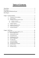
Table of Contents Optional Items ................................................................................................................. 6 Box Contents ................................................................................................................. 6 GA-M61SME-S2 Motherboard Layout ........................................................................... 7 Block Diagram ..............................................................................................................
Chapter 3 Drivers Installation ...................................................................................... 47 3-1 3-2 Install Chipset Drivers .................................................................................... 47 Software Applications ..................................................................................... 48 3-3 3-4 Driver CD Information .................................................................................... 48 Hardware Information ..................
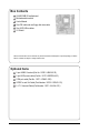
Box Contents GA-M61SME-S2 motherboard Motherboard driver disk User's Manual One IDE cable and one floppy disk drive cable One SATA 3Gb/s cables I/O Shield The box contents above are for reference only and the actual items shall depend on product package you obtain. The box contents are subject to change without notice. Optional Items 2-port USB 2.0 bracket (Part No. 12CR1-1UB030-51R) 2-port SATA power cable (Part No. 12CF1-2SERPW-01R) COM port cable (Part No.
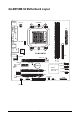
GA-M61SME-S2 Motherboard Layout KB_MS Socket AM2 COMA ATX_12V VGA LPT ATX CPU_FAN IT8716 F_AUDIO GA-M61SME-S2 CI IDE PCIE_16 DDRII_1 AUDIO HDA_SUR BIOS CLR_CMOS PCIE_1 DDRII_2 LAN USB R_USB SATAII 0 BATTERY Realtek 8201 PCI1 CD_IN nVIDIA ® GeForce 6100/ nForce 405 SATAII 1 F_USB2 F_USB1 PCI2 CODEC COMB FDD SYS_FAN PWR_LED SPDIF_IO -7- F_PANEL
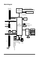
Block Diagram PCIe CLK (100 MHz) CPU CLK+/-(200 MHz) AMD Socket AM2 CPU DDRII 800/667/533/400 MHz DIMM Dual Channel Memory Hyper Transport Bus PCI Express x8 VGA PCI Express x1 Bus x1 2 SATA 3Gb/s nVIDIA® GeForce 6100/ nForce 405 PCIe CLK (100 MHz) ATA-33/66/100/133 IDE Channel 1 PCI Express x1 LAN RJ45 Floppy LPC BUS Realtek 8201 IT8716 LPT Port COM Ports PCI Bus PS/2 KB/Mouse BIOS 2 PCI PCI CLK (33 MHz) Surround Speaker Out Center/Subwoofer Speaker Out Side Speaker Out MIC Line-Out Line-
Chapter 1 Hardware Installation 1-1 Considerations Prior to Installation Preparing Your Computer The motherboard contains numerous delicate electronic circuits and components which can become damaged as a result of electrostatic discharge (ESD). Thus, prior to installation, please follow the instructions below: 1. Please turn off the computer and unplug its power cord. 2. When handling the motherboard, avoid touching any metal leads or connectors. 3.
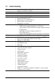
1-2 Feature Summary CPU Front Side Bus Chipset LAN Audio Storage O.
Rear Panel I/O I/O Control Hardware Monitor BIOS Additional Features Bundle Software Form Factor 1 PS/2 keyboard port 1 PS/2 mouse port 1 parallel port 1 COMA port 1 VGA port 4 USB 2.0/1.
1-3 Installation of the CPU and CPU Cooler Before installing the CPU, please comply with the following conditions: 1. Please make sure that the motherboard supports the CPU. 2. Please take note of the pin 1 marking (the small triangle) on the CPU. If you install the CPU in the wrong direction, the CPU will not insert properly. If this occurs, please change the insert direction of the CPU. 3. Please add an even layer of heat paste between the CPU and CPU cooler. 4.
1-3-2 Installation of the CPU Cooler Fig.1 Before installing the CPU cooler, please first add an even layer of heat paste on the surface of the CPU. Install all the CPU cooler components (Please refer to the cooler manual for detailed installation instructions). Fig.2 Please connect the CPU cooler power connector to the CPU_FAN connector located on the motherboard so that the CPU cooler can properly function to prevent CPU overheating.
1-4 Installation of Memory Before installing the memory modules, please comply with the following conditions: 1. Please make sure that the memory used is supported by the motherboard. It is recommended that memory of similar capacity, specifications and brand be used. 2. Before installing or removing memory modules, please make sure that the computer power is switched off to prevent hardware damage. 3. Memory modules have a foolproof insertion design. A memory module can be installed in only one direction.
Dual Channel Memory Configuration The GA-M61SME-S2 supports the Dual Channel Technology. After operating the Dual Channel Technology, the bandwidth of Memory Bus will double. Due to CPU limitation, if you wish to operate the Dual Channel Technology, follow the guidelines below: 1. Dual Channel mode will not be enabled if only one memory module is installed. 2. To enable Dual Channel mode with two memory modules, it is recommended to use memory modules of identical brand, size, chips and speed.
PCI Express x16 Graphics Card Support List The items below are all supported under the Windows XP operating system. When using an add-on graphics card, please first delete the onboard graphics driver before installing the driver for the add-on graphics card.
Graphics Chip ATi VIA 1-6 Maker Gigabyte Gigabyte Gigabyte Gigabyte Gigabyte Gigabyte Gigabyte Gigabyte Gigabyte Gigabyte ASUS ASUS MSI S3 Model Name GV-RX13P256D-RH GV-RX16P256DE-RH GV-RX18L256V-B GV-RX18T512V-B GV-RC19T512B-RH GV-RX165T256D-RH GV-RX13128D-RH GV-RX195P256D-RH GV-RX165P256D-RH GV-RX16T256V-RH AX800XT AX700PRO RX600 XT-TD128 GammaChrome S18 I/O Back Panel Introduction PS/2 Keyboard and PS/2 Mouse Connector To install a PS/2 port keyboard and mouse, plug the mouse to the upper port (gre
Line Out (Front Speaker Out) Connect the stereo speakers, earphone or front surround speakers to this connector. MIC In Microphone can be connected to MIC In jack. 1. You can use audio software to configure 2-/4-/6-/8-channel audio functioning. 2. To set up an 8 channel audio configuration, you must use 5.1/7.1 Surround Cable (optional).
1/2) ATX_12V/ATX (Power Connector) With the use of the power connector, the power supply can supply enough stable power to all the components on the motherboard. Before connecting the power connector, please make sure that all components and devices are properly installed. Align the power connector with its proper location on the motherboard and connect tightly. The ATX_12V power connector mainly supplies power to the CPU. If the ATX_12V power connector is not connected, the system will not start.
3/4) CPU_FAN / SYS_FAN (Cooler Fan Power Connector) The cooler fan power connector supplies a +12V power voltage via a 3-pin/4-pin (only for CPU_FAN) power connector and possesses a foolproof connection design. Most coolers are designed with color-coded power connector wires. A red power connector wire indicates a positive connection and requires a +12V power voltage. The black connector wire is the ground wire (GND).
6) FDD (FDD Connector) This connector is used to connect a floppy disk drive. The types of floppy disk drives supported are: 360 KB, 720 KB, 1.2 MB, 1.44 MB, and 2.88 MB. Before connecting a floppy disk drive, be sure to locate pin 1 of the connector and the floppy disk drive cable. The pin 1 of the cable is typically designated by a stripe of different color. 33 1 34 2 7) SATAII 0 / SATAII 1 (SATA 3Gb/s Connectors) SATA 3Gb/s can provide up to 300 MB/s transfer rate.
8) PWR_LED The PWR_LED connector is connected with the system power indicator to indicate whether the system is on/off. It will blink when the system enters suspend mode(S1). Pin No. 1 1 Definition MPD+ 2 3 MPDMPD- 9) F_PANEL (Front Panel Jumper) Please connect the power LED, PC speaker, reset switch and power switch etc. of your chassis front panel to the F_PANEL connector according to the pin assignment below.
10) F_AUDIO (Front Audio Connector) This connector supports either HD (High Definition) or AC97 front panel audio module. If you wish to use the front audio function, connect the front panel audio module to this connector. Check the pin assignments carefully while you connect the front panel audio module. Incorrect connection between the module and connector will make the audio device unable to work or even damage it. For optional front panel audio module, please contact your chassis manufacturer.
11) CD_IN (CD In Connector) Connect CD-ROM or DVD-ROM audio out to the connector. Pin No. 1 1 Definition CD-L 2 3 GND GND 4 CD-R 12) SPDIF_IO (S/PDIF In/Out Connector) The S/PDIF output is capable of providing digital audio to external speakers or compressed AC3 data to an external Dolby Digital Decoder. Use this feature only when your stereo system has digital input function. Use S/PDIF IN feature only when your device has digital output function.
13) HDA_SUR (Surround Center Connector) Attach the connector of the 5.1/7.1 Surround Cable (optional) to this connector. 2 14 1 13 Pin No. Definition 1 2 LEF_P SURR_RR 3 4 CEN_P SURR_LL 5 6 CEN_JD SURR_JD 7 8 GND -SUR_DET 9 10 GND No Pin 11 12 GND S_SURR_JD 13 14 S_SURR_LL S_SURR_RR 14) F_USB1 / F_USB2 / (Front USB Connectors) Be careful with the polarity of the front USB connector.
15) COMB (COMB Connector) Be careful with the polarity of the COMB connector. Check the pin assignments while you connect the COMB cable. Please contact your nearest dealer for optional COMB cable. Pin No. Definition 1 2 NDCDBNSINB 9 1 3 4 NSOUTB NDTRB- 10 2 5 6 GND NDSRB- 7 8 NRTSBNCTSB- 9 10 NRIBNo Pin 16) CI (Chassis Intrusion, Case Open) This 2-pin connector allows your system to detect if the chassis cover is removed. You can check the "Case Opened" status in BIOS Setup.
17) CLR_CMOS (Clear CMOS) You may clear the CMOS data to its default values by this header. To clear CMOS, temporarily short the two pins. Default doesn't include the jumper to avoid improper use of this header. Open: Normal Short: Clear CMOS 18) BATTERY Danger of explosion if battery is incorrectly replaced. Replace only with the same or equivalent type recommended by the manufacturer. Dispose of used batteries according to the manufacturer's instructions. If you want to erase CMOS... 1.
GA-M61SME-S2 Motherboard - 28 -
Chapter 2 BIOS Setup BIOS (Basic Input and Output System) includes a CMOS SETUP utility which allows user to configure required settings or to activate certain system features. The CMOS SETUP saves the configuration in the CMOS SRAM of the motherboard. When the power is turned off, the battery on the motherboard supplies the necessary power to the CMOS SRAM. When the power is turned on, pressing the button during the BIOS POST (Power-On Self Test) will take you to the CMOS SETUP screen.
: Boot Menu Select boot sequence for onboard (or add-on cards) device. Award Modular BIOS v6.00PG, An Energy Star Ally Copyright (C) 1984-2007, Award Software, Inc. GA-M61SME-S2 E7 . . . . :BIOS Setup/Q-Flash :Xpress Recovery2 :Boot Menu :Qflash 01/23/2007-NV-MCP61-6A61KG05C-00 :Boot Menu Use < > or < > to select a device, then press enter to accept . Press to exit this menu.
Standard CMOS Features This setup page includes all the items in standard compatible BIOS. Advanced BIOS Features This setup page includes all the items of Award special enhanced features. Integrated Peripherals This setup page includes all onboard peripherals. Power Management Setup This setup page includes all the items of Green function features. PnP/PCI Configuration This setup page includes all the configurations of PCI & PnP ISA resources.
2-1 Standard CMOS Features CMOS Setup Utility-Copyright (C) 1984-2007 Award Software Standard CMOS Features ` ` ` ` Date (mm:dd:yy) Time (hh:mm:ss) Mon, Mar 5 2007 14:42:37 IDE Channel 0 Master IDE Channel 0 Slave IDE Channel 2 Master IDE Channel 3 Master [None] [None] [None] [None] Drive A Floppy 3 Mode Support [1.44M, 3.
Access Mode Use this to set the access mode for the hard drive. The two options are: Large/Auto(default: Auto) Capacity Capacity of currently installed hard disk. Hard drive information should be labeled on the outside drive casing. Enter the appropriate option based on this information.
2-2 Advanced BIOS Features CMOS Setup Utility-Copyright (C) 1984-2007 Award Software Advanced BIOS Features AMD K8 Cool&Quiet control ` Hard Disk Boot Priority First Boot Device Second Boot Device Third Boot Device Password Check HDD S.M.A.R.T.
HDD S.M.A.R.T. Capability This feature allows your hard disk to report read/write errors and to issue warnings when thirdparty hardware monitor utility is installed. Enabled Enable HDD S.M.A.R.T. capability. Disabled Disable HDD S.M.A.R.T. capability. (Default value) Away Mode Disabled Enabled Disable this function. (Default value) Enable Away Mode in Windows XP Media Center operating system. (Away Mode: Enables the system to silently perform unattended tasks while in a low-power mode that appears off.
2-3 Integrated Peripherals CMOS Setup Utility-Copyright (C) 1984-2007 Award Software Integrated Peripherals ` Serial-ATA RAID Config On-Chip IDE Channel0 On-Chip MAC Lan NV Serial-ATA 1 IDE Prefetch Mode USB Memory Type Onboard Audio Function Onboard LAN Boot ROM Onboard Serial Port 1 Onboard Serial Port 2 Onboard Parallel Port Parallel Port Mode x ECP Mode Use DMA On-Chip USB USB Keyboard Support USB Mouse Support Legacy USB Storage detect KLJI: Move Enter: Select F5: Previous Values [Press Enter] [Ena
NV SATA RAID function Enabled Disabled Enable NV SATA RAID function. Disable NV SATA RAID function. (Default value) NV SATA 1 Primary RAID Enabled Disabled Enable NV SATA 1 primary RAID function. Disable this function. (Default value) NV SATA 1 Secondary RAID Enabled Disabled Enable NV SATA 1 secondary RAID function. Disable this function. (Default value) On-Chip IDE Channel0 Enabled Disabled Enable onboard 1st channel IDE port. (Default value) Disable onboard 1st channel IDE port.
Onboard Serial Port 2 Auto 3F8/IRQ4 2F8/IRQ3 3E8/IRQ4 2E8/IRQ3 Disabled BIOS will automatically setup the port 2 address. Enable onboard Serial port 2 and address is 3F8/IRQ4. Enable onboard Serial port 2 and address is 2F8/IRQ3. (Default value) Enable onboard Serial port 2 and address is 3E8/IRQ4. Enable onboard Serial port 2 and address is 2E8/IRQ3. Disable onboard Serial port 2. Onboard Parallel Port Disabled 378/IRQ7 278/IRQ5 3BC/IRQ7 Disable onboard LPT port.
2-4 Power Management Setup CMOS Setup Utility-Copyright (C) 1984-2007 Award Software Power Management Setup ACPI Suspend Type Soft-Off by Power button PME Event Wake Up Modem Ring On USB Resume from Suspend Power-On by Alarm x Day of Month Alarm x Time (hh:mm:ss) Alarm HPET Support (Note) HPET Mode (Note) Power On By Mouse Power On By Keyboard x KB Power ON Function AC Back Function KLJI: Move Enter: Select F5: Previous Values [S1(POS)] [Instant-off] [Enabled] [Enabled] [Enabled] [Disabled] Everyday 0:0
Power-On by Alarm You can enable the "Power-On by Alarm" item and key in Date/Time to power on system. Disabled Disable this function. (Default value) Enabled Enable alarm function to POWER ON system. If Power-On by Alarm is Enabled. Day of Month Alarm : Everyday, 1~31 Time (hh: mm: ss) Alarm : (0~23) : (0~59) : (0~59) HPET Support (Note) Disabled Enabled Disable this function. Enable support for High Precision Event Timer (HPET) funtion.
2-5 PnP/PCI Configurations CMOS Setup Utility-Copyright (C) 1984-2007 Award Software PnP/PCI Configurations PCI 1 IRQ Assignment PCI 2 IRQ Assignment KLJI: Move Enter: Select F5: Previous Values [Auto] [Auto] +/-/PU/PD: Value F6: Fail-Safe Defaults Item Help Menu Level` F10: Save ESC: Exit F1: General Help F7: Optimized Defaults PCI 1 IRQ Assignment Auto 3,4,5,7,9,10,11,12,14,15 Auto assign IRQ to PCI 1. (Default value) Set IRQ 3,4,5,7,9,10,11,12,14,15 to PCI 1.
2-6 PC Health Status CMOS Setup Utility-Copyright (C) 1984-2007 Award Software PC Health Status Reset Case Open Status Case Opened Vcore DDR2 1.8V +3.
CPU Smart FAN Control(Note) Disabled Enabled Disable this function. When this function is enabled, CPU fan will run at different speed depending on CPU temperature. Users can adjust the fan speed with Easy Tune based on their requirements. (Default value) CPU Smart FAN Mode This option is available only when CPU Smart FAN Control is enabled. Auto BIOS autodetects the type of CPU fan you installed and sets the optimal CPU Smart FAN control mode for it.
2-7 Load Fail-Safe Defaults CMOS Setup Utility-Copyright (C) 1984-2007 Award Software ` ` ` ` ` ` Standard CMOS Features Advanced BIOS Features Integrated Peripherals Power Management Setup PnP/PCI Configurations PC Health Status Load Fail-Safe Defaults Load Optimized Defaults Set Supervisor Password Set User Password Load Fail-Safe DefaultsSave (Y/N)? N Setup & Exit Exit Without Saving KLJI: Select Item F10: Save & Exit Setup ESC: Quit F8: Q-Flash Load Fail-Safe Defaults Fail-Safe defaults contain th
2-9 Set Supervisor/User Password CMOS Setup Utility-Copyright (C) 1984-2007 Award Software ` Standard CMOS Features Load Fail-Safe Defaults ` Advanced BIOS Features ` Integrated Peripherals ` ` Power Management Setup Enter Password: PnP/PCI Configurations ` PC Health Status Load Optimized Defaults Set Supervisor Password Set User Password Save & Exit Setup Exit Without Saving KLJI: Select Item F10: Save & Exit Setup ESC: Quit F8: Q-Flash Change/Set/Disable Password When you select this funct
2-10 Save & Exit Setup CMOS Setup Utility-Copyright (C) 1984-2007 Award Software ` Standard CMOS Features ` Advanced BIOS Features ` Integrated Peripherals ` Power Management Setup ` PnP/PCI Configurations ` PC Health Status Load Fail-Safe Defaults Load Optimized Defaults Set Supervisor Password Set User Password Save to CMOS and EXIT (Y/N)? Y & Exit Setup Save Exit Without Saving KLJI: Select Item F10: Save & Exit Setup ESC: Quit F8: Q-Flash Save Data to CMOS Type "Y" will quit the Setup Ut
Chapter 3 Drivers Installation For Windows XP/2000 operating system, please install the NVIDIA® GeForceTM 6100/nForceTM Series Utility CD. For Windows Vista operating system, please install the NVIDIA ® Series Vista Utility CD. Pictures below are shown in Windows XP. Insert the driver CD-title that came with your motherboard into your CD-ROM drive, the driver CD-title will auto start and show the installation guide. If not, please double click the CD-ROM device icon in "My computer", and execute the Run.
3-2 Software Applications This page displays all the tools that Gigabyte developed and some free software, you can choose anyone you want and press "install" to install them. 3-3 Driver CD Information This page lists the contents of software and drivers in this CD-title.
3-4 Hardware Information This page lists all device you have for this motherboard. 3-5 Contact Us Please see the last page for details.
GA-M61SME-S2 Motherboard - 50 -
Chapter 4 4-1 Appendix Unique Software Utilities (Not all model support these Unique Software Utilities, please check your MB features.) 4-1-1 EasyTune 5 Introduction EasyTune 5 presents the most convenient Windows based system performance enhancement and manageability utility. Featuring several powerful yet easy to use tools such as 1) Overclocking for enhancing system performance, 2) C.I.A. and M.I.B.
4-1-2 Xpress Recovery2 Introduction Xpress Recovery2 is designed to provide quick backup and restoration of hard disk data. Supporting Microsoft operating systems including Windows XP/2000/NT/98/Me and DOS, and file systems including FAT16, FAT32, and NTFS, Xpress Recovery2 is able to back up data on hard disks on PATA and SATA IDE controllers. After Xpress Recovery2 is executed from CD-ROM for the first time, it will stay permanent in your hard disk.
The Main Screen of Xpress Recovery2 1. RESTORE: Restore the backed-up data to your hard disk. (This button will not appear if there is no backup file.) 2. BACKUP: Back up data from hard disk. 3. REMOVE: Remove previously-created backup files to release disk space. (This button will not appear if there is no backup file.) 4. REBOOT: Exit the main screen and restart the system. Limitations: 1. 2. 3. Not compatible to Xpress Recovery. For the use of Xpress Recovery2, a primary partition must be reserved.
4-1-3 Flash BIOS Method Introduction Method 1 : Q-Flash TM Q-FlashTM is a BIOS update tool that allows the user to update BIOS without entering operating systems like MS-DOS or Windows.Embedded in the BIOS, the Q-FlashTM tool frees you from the hassles of going through complicated BIOS flashing process. Before Use: Follow the steps below before using Q-Flash to update BIOS: 1. From GIGABYTE's website, download the latest compressed BIOS update file that matches your motherboard model. 2.
c. Select the BIOS file and press ENTER. Make sure again the BIOS file matches your motherboard model. Step 2: The process of system reading the BIOS file from the floppy disk is displayed on the screen. When the message "Are you sure to update BIOS?" appears, press ENTER. The BIOS update will begin and the current process will be displayed. 1. Do not turn off or restart the system when the system is reading/updating the BIOS. 2.
Method 2 : @BIOSTM Utility If you do not have a DOS startup disk, we recommend that you use the new @BIOS utility. @BIOS allows users to update their BIOS under Windows. Just select the desired @BIOS server to download the latest version of BIOS. Fig 1. Installing the @BIOS utility Fig 2. Installation Complete and Run @BIOS Click Start/ Programs/ GIGABYTE/@BIOS Select @BIOS item than click Install Fig 3. The @BIOS Utility Click " " Fig 4. Select the desired @BIOS server Click "Update New BIOS" 1.
III. Save BIOS In the very beginning, there is "Save Current BIOS" icon shown in dialog box. It means to save the current BIOS version. IV. Check out supported motherboard and Flash ROM: In the very beginning, there is "About this program" icon shown in dialog box. It can help you check out which kind of motherboard and which brand of Flash ROM are supported. 2. Note: I. In method I, if it shows two or more motherboard's model names to be selected, please make sure your motherboard's model name again.
4-1-4 Configuring SATA Hard Drive(s) To configure SATA hard drive(s), follow the steps below: (1) Install SATA hard drive(s) in your system. (2) Configure SATA controller mode and boot sequence in BIOS Setup. (3) Configure RAID set in RAID BIOS. (Note ) (4) Make a floppy disk containing the SATA controller driver. (Note ) (5) Install the SATA controller driver during OS installation. (Note ) Before you begin Please prepare: (a) SATA hard drive(s).
(2) Configuring SATA controller mode and boot sequence in BIOS Setup You have to make sure whether the SATA controller is configured correctly in system BIOS Setup and set BIOS boot sequence for the SATA hard drive(s)/RAID array. Step 1: Turn on your computer and press Del to enter BIOS Setup during POST (Power-On Self Test). In the example in Figure 1, make sure that NV Serial-ATA 1 under the Integrated Peripherals menu is enabled.
Step 2: To boot from Windows installation CD-ROM disk, set First Boot Device under the Advanced BIOS Features menu to CDROM (Figure 3). CMOS Setup Utility-Copyright (C) 1984-2007 Award Software Advanced BIOS Features AMD K8 Cool&Quiet control ` Hard Disk Boot Priority First Boot Device Second Boot Device Third Boot Device Password Check HDD S.M.A.R.T.
(3) Configuring RAID set in RAID BIOS Enter the RAID BIOS setup utility to configure a RAID array. Skip this step if you do not want to create RAID. Step 1: After the POST memory test begins and before the operating system boot begins, look for a message which says "Press F10 to enter RAID setup utility" (Figure 4). Hit the F10 key to enter the RAID BIOS setup utility. MediaShield IDE ROM BIOS 6.87 Copyright (C) 2006 NVIDIA Corp. Detecting array ... Press F10 to enter RAID setup utility ...
Step 5: Next, select the hard drives which you wish to be included in the disk array. The Free Disks section displays the information about the currently installed SATA hard drives. Press the TAB key to move to the Free Disks section. Select the target hard drives using the UP or DOWN ARROW key and use the RIGHT ARROW key to add the hard drives to the Array Disks section (Figure 6).
After that, the Array List screen displaying the RAID array you created will appear (Figure 8). (Note: BBS stands for BIOS Boot Specification. This indicates that the boot device is defined in the BIOS.) MediaShield Utility Aug 21 2006 - Array List Boot Status Vendor Array Model Name BBS Healthy NVIDIA STRIPE 223.
(4) Making a SATA Driver Disk To install operating system onto RAID disks successfully, you need to install the SATA RAID driver during OS installation. Without the driver, the hard disk may not be recognized during the Windows setup process. Skip this step if you do not want to create RAID. First of all, copy the driver for the SATA controller from the motherboard driver CD-ROM to a floppy disk. See the instructions below about how to copy the driver in MS-DOS mode (Note).
(5) Installing SATA controller driver during OS installation Now that you have prepared the SATA driver disk and configured BIOS settings, you are ready to install Windows 2000/XP onto your SATA hard drive with the SATA driver. The following is an example of Windows XP installation. Step 1: Restart your system to boot from the Windows 2000/XP Setup disk and press F6 as soon as you see the "Press F6 if you need to install a 3rd party SCSI or RAID driver" message (Figure 13).
Step 3: If Setup correctly recognizes the driver in the floppy disk, a controller menu similar to Figure 15 below will appear. Use the ARROW keys to select NVIDIA RAID CLASS DRIVER (Figure 15) and press ENTER. Later, when a screen similar to Figure 16 appears, you must press S to select additional driver. The screen will return to previous screen as shown in Figure 15. Select NVIDIA nForce Storage Controller and press ENTER.
Step 4: When the next screen (Figure 17) appears, press ENTER to continue the SATA driver installation from the floppy disk. Windows Setup Setup will load support for the following mass storage device(s): NVIDIA RAID CLASS DRIVER (required) NVIDIA nForce Storage Controller (required) * To specify additional SCSI adapters, CD-ROM drives, or special disk controllers for use with Windows, including those for which you have a device support disk from a mass storage device manufacturer, press S.
4-1-5 2- / 4- / 6- / 8- Channel Audio Introduction This motherboard comes with three audio jacks. To set up multichannel surround sound, install an additional 5.1/7.1 surround cable (optional) and enable the feature through the audio driver. Installing the 5.1/7.1 Surround Cable (Optional) The 5.1/7.1 Surround Cable provides center/ subwoofer speaker out, rear speaker out, and side speaker out audio jacks. To set up multi-channel surround sound, this cable needs to be installed. Step: 1. Connect the 5.
HD Audio With multiple built-in high quality digital-to-analog converters (DACs) that support audio output at up to 192 kHz/24-bit quality and multi-streaming applications, HD Audio is able to handle multiple audio streams (in and out) simultaneously. Multi-channel audio experiences have become a reality so you can, for instance, listen to MP3 music, have an Internet chat, make a telephone call over the Internet, and etc. all at the same time.
Setting Up 4-Channel Audio STEP 1 : After installation of the audio driver, you should find an Audio Manager icon in your system tray (you can also find the icon in Control Panel). Doubleclick the icon to open the Audio Control Panel. STEP 2: In the Audio Control Panel, click the Audio I/O tab. In the upper left list, click 4CH Speaker.
Setting Up 6-Channel Audio STEP 1 : After installation of the audio driver, you should find an Audio Manager icon in your system tray (you can also find the icon in Control Panel). Doubleclick the icon to open the Audio Control Panel. STEP 2: In the Audio Control Panel, click the Audio I/O tab. In the upper left list, click 6CH Speaker.
Setting Up 8-Channel Audio STEP 1 : After installation of the audio driver, you should find an Audio Manager icon in your system tray (you can also find the icon in Control Panel). Doubleclick the icon to open the Audio Control Panel. STEP 2: In the Audio Control Panel, click the Audio I/O tab. In the upper left list, click 8CH Speaker.
Sound Effect Configuration: At the Sound Effect menu, users can adjust sound option settings as desired. AC'97 Audio Configuration: To enable the front panel audio connector to support AC97 Audio mode, go to the Audio Control Panel and click the Audio I/O tab. In the ANALOG area, click the Tool icon and then select the Disable front panel jack detection check box. This action completes the AC'97 Audio configuration.
4-2 Troubleshooting 4-2-1 Frequently Asked Questions To read more FAQs for your motherboard, please go to the Support\Motherboard\FAQ page on GIGABYTE's website. Q: In the BIOS Setup program, why are some BIOS options missing? A: Some advanced options are hidden in the BIOS Setup program. Press to enter BIOS Setup during the POST. In the Main Menu, press + to show the advanced options.
4-2-2 Troubleshooting Procedure If you encounter any troubles during system startup, follow the troubleshooting procedure below to solve the problem. START Turn off the power. Remove all peripherals, connecting cables, and power cord etc. Make sure the motherboard does not short-circuit with the chassis or other metal objects. No Yes Isolate the short circuit. The problem is verified and solved. Check if the CPU cooler is attached to the CPU securely.
A When the computer is turned on, is the CPU cooler running? Yes No The power supply, CPU or CPU socket might fail. The problem is verified and solved. Check if there is display on your monitor. Yes No The graphics card, expansion slot, or monitor might fail. The problem is verified and solved. Turn off the computer. Plugg in the keyboard and mouse and restart the computer. Check if the keyboard is working properly. No The keyboard or mouse might fail. Yes Press to enter BIOS Setup.
Regulatory Statements Regulatory Notices This document must not be copied without our written permission, and the contents there of must not be imparted to a third party nor be used for any unauthorized purpose. Contravention will be prosecuted. We believe that the information contained herein was accurate in all respects at the time of printing. GIGABYTE cannot, however, assume any responsibility for errors or omissions in this text.
Finally, we suggest that you practice other environmentally friendly actions by understanding and using the energy-saving features of this product (where applicable), recycling the inner and outer packaging (including shipping containers) this product was delivered in, and by disposing of or recycling used batteries properly.
Contact Us Taiwan (Headquarters) China GIGA-BYTE TECHNOLOGY CO., LTD. Address: No.6, Bau Chiang Road, Hsin-Tien, NINGBO G.B.T. TECH. TRADING CO., LTD. WEB address : http://www.gigabyte.cn Taipei 231, Taiwan TEL: +886-2-8912-4888 Shanghai TEL: +86-21-63410999 FAX: +886-2-8912-4003 Tech. and Non-Tech. Support (Sales/Marketing) : FAX: +86-21-63410100 Beijing http://ggts.gigabyte.com.tw WEB address (English): http://www.gigabyte.com.
Germany Russia G.B.T. TECHNOLOGY TRADING GMBH WEB address : http://www.gigabyte.de Moscow Representative Office Of GIGA-BYTE Technology Co., Ltd. U.K. G.B.T. TECH. CO., LTD. WEB address : http://www.gigabyte.ru Latvia WEB address : http://www.giga-byte.co.uk The Netherlands GIGA-BYTE Latvia WEB address : http://www.gigabyte.lv GIGA-BYTE TECHNOLOGY B.V. WEB address : http://www.giga-byte.nl Poland Office of GIGA-BYTE TECHNOLOGY Co., Ltd. in POLAND Sweden WEB address : http://www.gigabyte.