AMD Limit Switch For Series instrumentation for fluids M21 / ADI15 Instructions Manual C-MI-AMDM21/ADI Rev.
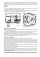
The AMD limit switch consists of a NAMUR slot type inductive sensor, that is actuated by a vane. Given that there is no physical contact in the operation, the limit switch has no influence on the indicator needle movement. A NAMUR amplifier with a relay output can be supplied as an optional element. OPERATION The indicator needle moves together with the vane mounted on its shaft. When the vane enters into the slot of the detector, the limit switch changes its state.
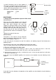
In some instruments such as some models of ADI series, instead of having a connector, there is a cable gland with a cable with three colours (brown, blue and green/yellow). In this case the connections should be made as follows: Green/yellow Brown Blue 3 2 Sin conexión No connection 1 _ (azul) (Blue) + (marrón) (Brown) Tierra Earth = Earth = + = - MAINTENANCE 1.
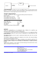
+ + Multimeter mA NAMUR Connection Amplifier Potentiometer 20 kΩ With the potentiometer we modify the current of the NAMUR amplifier. The switching point must be between 1.2 mA and 2.1 mA. That is, with the current below 1.2 mA the output relay must have a state and above 2.1 mA the output relay must have the other state.