PPC-L106T AMD LX800 processor-based Panel PC with 10.
Copyright This document is copyrighted, © 2006. All rights are reserved. The original manufacturer reserves the right to make improvements to the products described in this manual at any time without notice. No part of this manual may be reproduced, copied, translated or transmitted in any form or by any means without the prior written permission of the original manufacturer. Information provided in this manual is intended to be accurate and reliable.
FCC Class B This equipment has been tested and found to comply with the limits for a Class B digital device, pursuant to Part 15 of the FCC Rules. These limits are designed to provide reasonable protection against harmful interference when the equipment is operated in a residential environment. This equipment generates, uses and can radiate radio frequency energy. If not installed and used in accordance with this user manual, it may cause harmful interference to radio communications.
Packing List Before you begin installing your card, please make sure that the following materials have been shipped: • PPC-L106T series panel PC • Accessories for PPC-L106T - Keyboard extension cable (5-pin DIN female to 6-pin PS/2 male) - HDD flat cable (44-pin) (8 cm) - Power cord (1.8 m) - USA type - HDD bracket - Driver/Utility CD-ROM disk - Screws - Warranty card If any of these items are missing or damaged, contact your distributor or sales representative immediately.
Safety Instructions 1. Please read these safety instructions carefully. 2. Please keep this User Manual for later reference. 3. Please disconnect this equipment from any AC outlet before cleaning. Do not use liquid or spray detergents for cleaning. Use a damp cloth. 4. For pluggable equipment, the socket-outlet must be installed near the equipment and must be easily accessible. 5. Please keep this equipment away from humidity. 6. Put this equipment on a reliable surface during installation.
Wichtige Sicherheishinweise 1. Bitte lesen sie Sich diese Hinweise sorgfältig durch. 2. Heben Sie diese Anleitung für den späteren Gebrauch auf. 3. Vor jedem Reinigen ist das Gerät vom Stromnetz zu trennen. Verwenden Sie Keine Flüssig-oder Aerosolreiniger. Am besten dient ein angefeuchtetes Tuch zur Reinigung. 4. Die NetzanschluBsteckdose soll nahe dem Gerät angebracht und leicht zugänglich sein. 5. Das Gerät ist vor Feuchtigkeit zu schützen. 6.
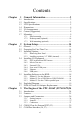
Contents Chapter 1 General Information ........................................2 1.1 1.2 1.3 1.4 1.5 1.6 1.7 Introduction ....................................................................... 2 Specifications .................................................................... 2 LCD Specifications ........................................................... 5 Dimensions........................................................................ 6 I/O Arrangement ..............................................
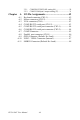
3.5.1 3.5.2 Chapter COM2 RS-232/422/485 setting (J6) ............................. 29 COM3/COM4 pin 9 output setting (J7)........................ 31 A I/O Pin Assignments.......................................42 A.1 A.2 A.3 A.4 A.5 A.6 A.7 A.8 A.9 A.10 A.11 Keyboard connector (CN5-1).......................................... 42 Mouse connector (CN5-2)............................................... 42 VGA connector (CN6) ....................................................
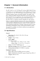
CHAPTER 1 General Information This chapter gives background information on the PPC-L106T.
Chapter 1 General Information 1.1 Introduction The PPC-L106T is a 10.4" LCD Panel PC with an AMD LX800 CPU that is designed to serve as a human machine interface (HMI). It is a PC-based system with 10.4" color TFT LCD display, on-board PCI Ethernet, multiCOM port interfaces, and a 16-bit audio controller. This simple, complete, compact and highly integrated multimedia system lets you easily build a panel PC into your applications.
• 2nd level cache: 128 KB on CPU • RAM: One 200-pin SODIMM sockets accept 256 ~ 1024 MB DDR • PCI Bus Master IDE interface: Supports two connectors (one internal, one external). Each connector supports two IDE devices on two channels (PIO modes 3/4). BIOS supports IDE (PIO mode 0~4, DMA mode 0~2, and Ultra DMA33 simultaneously). Default: CF Slot set as Master • Parallel port: One parallel port, supports SPP/EPP/ECP parallel mode.
• Ethernet Chipset: Realtek RTL8100C PCI local bus Ethernet controller fully compliant with IEEE 802.3u 10/100 Base-T specifications.
1.3 LCD Specifications Default Optional Display type (LCD) 10.4" SVGA TFT 10.4" SVGA TFT Max. resolution 800 x 600 800 x 600 Colors 262 K colors 262 K colors View angle 120 / 100 140 / 100 Dot size (mm) 0.264 X 0.264 0.264 X 0.
1.4 Dimensions Figure 1.
1.5 I/O Arrangement Figure 1.2: PPC-L106T back panel I/O arrangement and cable connections A. Power switch F. COM ports B. Parallel port G. COM ports C. PS/2 mouse connector H. VGA port D. Mic-in/Line-out I. USB ports V2.0 E. AC inlet J.
1.6 Cutout (Suggestion) The PPC-L106T will stand on a shelf or a table, or you can mount it into a panel. Cutout panel dimensions are as follows Figure 1.
1.7 Mounting 1.7.1 Panel mounting If you decide to use a cutout within a panel to mount your PPC-L106T, we have included two panel-mount brackets. The brackets have two screws that fit in the keyhole slots on the panel PC. Slide the PPC-L106T backwards into the panel opening. Attach the two mounting brackets by sliding the two screw heads into the keyhole slots on the rear cover. Secure the PPC-L106T against the back of the panel opening. Figure 1.
1.7.2 Desktop stand (optional) An optional stand is available for mounting the PPC as a desktop PC. The PPC-L106T slides into the stand and is held in place by the screws provided. The compactness of the desktop-mounted PPC-L106T saves desk space. Figure 1.
1.7.3 Wall-mounting (optional) An optional wall-mounting attachment is also available for mounting the PPC at approximately 45° to a flat surface. Installation instructions follow: 1. The wall-mounting attachment is comprised of three parts: one back bracket, one support bracket, and one mounting bracket. 2. First attach the back bracket to the rear cover of the PPC-L106T, securing it in place with four of the philips-head screws provided. 3.
12 PPC-L106T User Manual
CHAPTER 2 System Setup Sections include: • General • Removing Rear Panel • Installing Options • Installing I/O Equipment • Installing Software to the HDD • Exploded Diagram • PCM-9679 and I/O Adapter • Replacement • Power Supply and Cooling Fan • Replacement Chapter 2 System Setup 13
Chapter 2 System Setup 2.1 General The PPC-L106T consists of a PC-based industrial computer that is housed in a protective cover. Your HDD, DDR RAM and power supply and are all readily accessible by removing the rear panel. Any maintenance or hardware upgrades can be carried out easily after removing the rear panel. Warning! Do not remove the rear cover until you have verified that no power is flowing within the PPCL106T. Power must be switched off, and the power cord must be disconnected.
2.3 Installing Options 2.3.1 Removing Rear Panel Unscrew the eleven screws that secure the rear cover, then remove the cover. Figure 2.
2.3.2 Installing a primary 2.5" HDD (internal) You can attach one enhanced Integrated Device Electronics (IDE) hard disk drive to the PPC-L106T's internal controller which uses a PCI localbus interface. The advanced IDE controller supports faster data transfer rates and allows the IDE hard drive to exceed 528 MB. The following are instructions for installation: 1. Detach the rear panel and remove. 2. Place the HDD in the appropriate location inside the PPC-L106T, and tighten the screws. 3.
2.4 Installing I/O Equipment 2.4.1 PS/2 keyboard and PS/2 mouse The PPC-L106T provides a PS/2 keyboard connector that supports a PS/2 style keyboard and a 5-pin DIN keyboard extension cable. In most cases, especially in embedded applications, a keyboard is not used. The standard PC/AT BIOS will report an error or failure during power-on self-test (POST) after a reset if the keyboard is not present. The BIOS standard setup menu allows you to select* "All, But Keyboard" under the "Halt On" selection.
2.4.5 Ethernet The PPC-L106T is equipped with a high performance 32-bit Ethernet chipset which is fully compliant with the IEEE 802.3 100 Mbps CSMA/ CD standards. It is supported by major network operating systems. It is also both 100Base-T and 10Base-T compatible. The medium type can be configured via the RSET8139.EXE program included on the utility disk. The Ethernet port provides a standard RJ-45 jack.
2.6 Exploded Diagram Figure 2-3 shows all the components and parts that make up the PPCL106T. Use it as a guide when assembling and disasesembling your system. Figure 2.
2.7 PCM-9679 and I/O Adapter Replacement To replace or service the PCM-9679 (all-in-one CPU board) and I/O adapter, complete the following steps: 1. Turn off the power to the PPC-L106T 2. Remove the rear protective cover (see Figure 2-1) 3. Install the PCM-9679 in the panel and screw in the eight screws (see Figure 2-4) 4. When the PCM-9679 is mounted in the panel, plug and press the adapter into the socket (see Figure 2-4)) 5.
Figure 2.
22 PPC-L106T User Manual
CHAPTER 3 The Engine of the PPC-L106T (PCM-9679) Sections include: • Introduction • Features • Jumpers and Connectors • CMOS clear • Watchdog timer configuration • COM2 RS-232/422/485setting Chapter 3 System Setup 23
Chapter 3 The Engine of the PPC-L106T (PCM-9679) 3.1 Introduction The PCM-9679 is a highly reliable single board computer based on the AMD LX800 CPU. It offers built-in functionality comparable to a complete industrial PC system, including a VGA/LCD controller, network communications, CompactFlash disk in a small 8" x 5.75" form factor. For maximum performance, the PPC-L106T also supports a DDR SODIMM socket that can accept up to 1024 MB memory.
3.2 Features • Ultra-compact size single board computer as small as a 3 1/2" hard disk drive (145 mm x 102 mm) • On-board AMD LX800 CPU • Up to 1024 MB system memory via an SODIMM (DDR) • On-board VGA/LCD controller • On-board 10/100Base-T Ethernet interface (dual LAN Optional) • Supports on-board CompactFlash™ socket • Built-in Enhanced IDE (AT bus) hard disk drive interface • Four serial ports: three RS-232, one RS-232/422/485 or infared selectable • Supports One Mini PCI socket • Supports 4 USB 2.
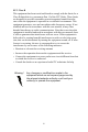
3.3 Jumpers and Connectors 3.3.1 Setting jumpers You can configure your panel PC to match the needs of your application by setting jumpers. A jumper is the simplest kind of electrical switch. It consists of two metal pins and a small metal clip (often protected by a plastic cover) that slides over the pins to connect them. To “close” a jumper, you connect the pins with the clip. To “open” a jumper you remove the clip. Sometimes a jumper will have three pins, labeled 1, 2, and 3.
3.3.2 Jumpers The table below lists the function of each of the board’s jumpers. Table 3.1: Jumpers and their functions S1 Reset Button J2 SMBUS Power Setting J3 CMOS Clear J4 AT/ATX Setting J6 COM2 RS232/422/485 Setting J7 COM3/4 Pin9 output type setting BT1 Battery Connector SLOT1 PCI/ISA bus expansion connector 3.3.3 Connectors The table below lists the function of each of the board's connectors. Table 3.
CN1 J2 H2 CN2 LVDS H3 SMBUS CN5 TOUCH-(COM4) CN3 H1 J2 SMB_PWRSEL CN4 INVERTER U12 1 2 3 4 5 6 7 8 9 10 11 12 13 14 15 16 17 GPIO CN7 CN8 POWER INPUT A B C D E F G H J K L M N P R T U CN6 CN9 IDE H4 J3 INTERNAL USB J3 Clear CMOS J4 S1 SLOT1 CN11 CN13 IAS-5V/ -12VINPUT PWR_LED Reset Button BT1 H5 CN12 H6 J4 AT/ATX Sel CN14 MIO-(USB+COM3) CN15 MIO_(USB) SLOT1 CN17 INTERNAL LAN CN16 INTERNAL AUDIO OUT J7 J6 CN19 CN18 LINE_IN CN21 INTERNAL SPAKER BT1 J6 H9 CN20 H8
3.4 CMOS Clear for External RTC (J3) Warning! To avoid damaging the computer, always turn off the power supply before setting “Clear CMOS”. Set the jumper back to “Normal operation” before turning on the power supply. This jumper is used to erase CMOS data and reset system BIOS information. The procedure for clearing CMOS is: 1. Turn off system. 2. Short pin 2 and pin 3. 3. Return jumper to pins 1 and 2. 4. Turn on the system. The BIOS is now reset to its default setting. Table 3.
Table 3.4: COM2 RS-232/422/485 setting (J6) *RS-232 RS-422 RS-485 * default setting The IRQ and the address ranges for COM1, 2, 3, and 4 are fixed. However, if you wish to disable the port or change these parameters later you can do this in the system BIOS setup. The table overleaf shows the default settings for the panel PC’s serial ports. COM1 and COM2 are one set. You can exchange the address range and interrupt IRQ of COM1 for the address range and interrupt IRQ of COM2.
Table 3.5: Serial port default settings Port Address Range Interrupt COM1 3F8 ~ 3FF IRQ4 COM2 2F8 ~ 2FF IRQ3 COM3 3E8 ~ 3EF IRQ10 COM4 2E8 ~ 2EF IRQ5 3.5.2 COM3/COM4 pin 9 output setting (J7) Table 3.
32 PPC-L106T User Manual
APPENDIX A I/O Pin Assignments Sections include: Appendix A I/O Pin Assignments 41
Chapter A I/O Pin Assignments A.1 Keyboard connector (CN5-1) Table A.1: Keyboard connector Pin Signal 1 KB_DT 2 N/A 3 GND 4 +5 V 5 KB_CK 6 N/A A.2 Mouse connector (CN5-2) Table A.
A.3 VGA connector (CN6) Table A.3: VGA connector Pin Signal 1 RED 2 GREEN 3 BLUE 4 N/A 5 6 1 11 2 12 3 13 GND 4 14 6 GND 5 15 7 GND 8 GND 9 N/A 10 GND 11 N/A 12 N/A 13 HSYNC 14 VSYNC 15 N/A 10 A.4 COM1 RS-232 serial port (CN1-2) Table A.
A.5 COM3 RS-232 serial port connector (CN2-1) Table A.5: COM3 RS-232 serial port Pin Signal 1 DCD 2 RxD 3 TxD 4 DTR 5 GND 6 DSR 7 RTS 8 CTS 9 RI 1 2 3 4 5 A.6 COM4 RS-232 serial port connector (CN2-2) Table A.
A.7 COM2 Connector Table A.
A.8 Parallel port connector (CN1-1) Table A.
A.9 GPIO Connector (Default: No Load) Table A.9: CN7 GPIO Pin Signal Pin Signal 1 +V5 2 GPIO4 3 GPIO0 4 GPIO5 5 GPIO1 6 GPIO6 7 GPIO2 8 GPIO7 9 GPIO3 10 GND A.10 USB 3 / USB 4 Connector (Internal) Table A.
A.11 SMBUS Connector (Default :No Load) 1 2 3 4 Table A.