
User`s guide

6
I
DENTIFYING
E
XTERNAL
C
OMPONENTS
This section identifies all the major external components of the switch. Both the front and rear p
anel is shown, followed by a description of each panel’s feature.
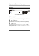
Front Panel
The figure below shows the front panels of the switch.
1
2
3
4
5
6
7
8
9
10 11 12 13 14 15 16
POWER
100Mbps
LINK
LINK
100Mbps
Switch
16-port 10/100Mbps Fast Ethernet Switch
LED Indicator Panel
Power (PWR)
This indicator lights green when the switch is receiving power, otherwise, it is
off.
Link / Activity ( green )
This indicator lights green when the port is connected to a Fast Ethernet or
Ethernet station. The indicator blinks green when transmitting or receiving
data.
100Mbps ( green )
This LED indicator lights green when the port is connected to a 100Mbps
Fast Ethernet station. Otherwise, the LED is off when the port is connected to
a 10Mbps Ethernet station.