SS2GD8I 6-port 10/100/1000 + 2 Combo-SFP Port L2 Managed Switch User’s Guide Version 1.
Amer.com 6901 Bryan Dairy Road, Suite 150, Largo, FL 33777 © Amer.com Corp., 1997-2006 All rights reserved. No part of this publication may be reproduced in any form or by any means or used to make any derivative such as translation, transformation, or adaptation without permission from Amer.com, as stipulated by the United States Copyright Act of 1976. Amer.com reserves the right to make changes to this document and the products which it describes without notice. Amer.
Table of Contents 1 INTRODUCTION ................................................................................................................1 1.1 PRODUCT OVERVIEW ...................................................................................................1 1.2 KEY FEATURES OF THE SWITCH ....................................................................................1 1.3 CHECKLIST ...............................................................................................................
3.13 STP CONFIGURATION .................................................................................................43 3.13.1 STP Status ......................................................................................................43 3.13.2 Configuration...................................................................................................44 3.13.3 Port..................................................................................................................45 3.
Caution Circuit devices are sensitive to static electricity, which can damage their delicate electronics. Dry weather conditions or walking across a carpeted floor may cause you to acquire a static electrical charge. To protect your device, always: • Touch the metal chassis of your computer to ground the static electrical charge before you pick up the circuit device. • Pick up the device by holding it on the left and right edges only.
About this user’s manual This user’s manual will show you how to install and connect the switch to your network and also how to configure and monitor the switch through the built-in CLI and web interface through RS-232 serial interface and Ethernet with step-by-step instructions. Many explanations of hardware and software functions are shown as well as examples of the operation for the web-based graphical user interface (GUI) and command-line interface (CLI).
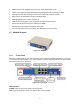
1 Introduction 1.1 Product Overview The SS2GD8I is a managed switch that meets all IEEE802.3/u/x/z Fast Ethernet and Gigabit specifications. The switch features 6 Gigabit copper ports and 2 Gigabit Combo-SFP ports. The switch can be managed through the RS-232 serial port or through an Ethernet port using either the CLI or Web GUI. With an SNMP agent, the network administrator can also log into the switch to monitor, configure and control the switch using SNMP.
• RS-232 Cable Please notify your sales representative immediately if any of the aforementioned items are missing or damaged. 1.4 Features The SS2GD8I switch provides the features listed below for users to perform system network administration and service the network efficiently and securely.
• SNMP access can be disabled and prevent from unauthorized SNMP access • Ingress, non-unicast and egress bandwidth rating management with a resolution of 1Mbps • The trap event and alarm message can be sent via e-mail and mobile phone SMS • Diagnostics to let administrators know the hardware status • External loopback test to check if the link is ok • TFTP for firmware upgrade, system log upload and config file import/export • Remote boot the device through user interface and SNMP • Network
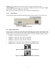
LINK/ACT: Lights up green when connected to a device, flashes when transmitting data. 10/100/1000Mbps: Lights up green when connected at 1000Mbps, amber when connected at 100Mbps, and is off when connected at 10Mbps or not connected. SFP: Lights up green when connected to a device, blinks when transmitting data. 1.5.2 Rear Panel The RS-232 port used for command line management and the power outlet are on the rear of the unit. Figure 1-3: Rear Panel 1.
2 Installation 2.1 Installing Switch into 19-Inch Rack Figure 2-1: Installing the Switch Caution: Allow proper spacing and air ventilation for the cooling fans on both sides of the switch. To installing the switch into the rack: 1. Wear a grounding device for electrostatic discharge. 2. Screw the mounting accessory into the sides of the switch (See Figure 2-1). 3. Place the switch into the 19-inch rack in the proper position, then screw the switch to the rack. 2.
SFP Transceivers The SFP slots are hot-swappable, meaning that SFP transceivers can be installed or removed while the switch is on. To install a transceiver: 1. Verify that the SFP module is the right type and form factor for the switch. 2. Slide the module completed into the slot, making sure that the module is properly seated against the connector in the back of the slot 3. Install the fiber cable to connect to the network 4.
The following table lists the types of fiber supported by the switch: IEEE 802.3z Gigabit Ethernet 1000SX 850nm 1000BaseLX/LHX/XD/ZX 1000Base-LX Fiber (BIDI LC) Single Multi-mode Fiber Cable and Modal Bandwidth Multi-mode 62.
Case 2a: Port-based VLAN (See Figure 2-4). Figure 2-4: Port-based VLAN Diagram 1. The same VLAN members cannot be connected to different switches. 2. Each VLAN member cannot access members of other VLANs. 3. The switch manager has to assign different names for each VLAN group on the switch. Case 2b: Port-based VLAN (See Figure 2-5). Figure 2-5: Port-based VLAN Diagram on Two Switches 1. VLAN1 members cannot access VLAN2, VLAN3 and VLAN4 members. 2.
Case 3: Tag-based VLANs. The same VLAN members can be at different switches with the same VID (See Figure 2-6). Figure 2-6: Tag-based VLAN Diagram 2.2.2 Configuring the Switch There are three ways to setup and manage the switch. They are via RS-232 console, command line interface (CLI), and web interface. Users can use any one of them to monitor and configure the switch. To configure the switch using a serial RS-232 connection, refer to Section 4 for connection instructions and the CLI reference.
4. Select Internet Protocol (TCP/IP), then click Properties. 5. Select to use a static IP address or “Use the following IP address”. 6. Enter the following IP address for the computer: “192.168.1.5” 7. Enter the following subnet mask for the computer: “255.255.255.0” 8. Click “OK” and save the settings. 9. Open up a web browser (e.g. Internet Explorer), and enter “http://192.168.1.1” in the address bar. 10. You should now be presented with the login page of the web interface (Figure 2-8).
3 Web Interface Using the web interface, you can monitor and control all aspects of the switch, including port status and activity, spanning tree status, port aggregation status, multicast traffic, VLAN and priority status, illegal access records. The default settings of the switch are as follows: IP Address 192.168.1.1 Subnet Mask 255.255.255.0 Default Gateway 192.168.1.254 Username admin Password Admin Table 3-1: Default Settings To connect and log into the switch, refer to section 2.2.2.
3.1 Home Page After you login, the switch will display the System Information page (figure 3-2). This page shows you some basic information about the switch, including “Model Name”, “System Description”, “Location”, “Contact”, “Device Name”, “System Up Time”, “Current Time”, “BIOS Version”, “Firmware Version”, “Hardware-Mechanical Version”, “Serial Number”, “Host IP Address”, “Host Mac Address”, “Device Port”, “RAM Size” and “Flash Size”.
Figure 3-3: Port Information Page On the left-top corner of the home page, there is a dropdown list to set the Auto Logout time. For security purposes, you will automatically be logged out after a period of inactivity. You can change the amount of time the switch waits before automatically logging you out by selecting a duration from this dropdown list. You can also disable the auto-logout feature by selecting “Off” from the list. Once you are logged out, you will need to log back in through the login page.
Firmware version: The firmware version on the switch. Hardware-Mechanical version: The hardware and mechanical version of the switch. The number before the hyphen is the hardware version; the one after the hyphen is the mechanical version. Serial number: The serial number as assigned by the manufacturer. Host IP address: The IP address of the switch. Host MAC address: The Ethernet MAC address the switch. Device Port: The types and numbers of ports in the switch.
Default gateway: Allows you to manually set the IP address for your network gateway, which is typically a router or bridge to the internet or other subnet. All packets which are addressed to a device that is not in the switch’s routing table will be sent to the default gateway. Default: 192.168.1.254 DNS: The Domain Name Server used to serve the translation between IP addresses and domain names. If set to “Manual”, it must be entered manually by the user.
Fall. Available choices for the time change are from -5 to +5 in one hour increments. Setting this to zero will disable daylight saving time. If the value is non-zero, you have to set the starting/ending date as well; otherwise the daylight saving function will not be activated. 3.1.4 Account Configuration The Account Configuration page under the System menu (Figure 3-6) allows you to manage the users who can manage the switch. Only administrators can create, modify or delete user accounts.
Figure 3-7: Management Policy Page Name: A name for the rule made up of letters and numbers up to 8 characters. VID: If set to “Any”, the rule applies to users from any VLAN, otherwise you can enter a specific VID to limit the rule. Valid VID range is from 1 to 4094. IP Range: If set to “Any”, the rule applies to users with any IP address, otherwise you can enter a range of IP addresses to restrict which users the rule will apply to. The valid IP range is from 0.0.0.0 to 255.255.255.255.
The button on the far left of the top row represents the master switch. The background color of the active switch will be highlight in green. Note: If you log into a switch using the console, it will disable the virtual stack temporarily. The name of the device is shown as the station address (the last number of the IP address) plus the name of the switch, concatenated with an underscore (e.g. 100_SS2GD8I) for a switch with an IP address 192.168.0.100 and name “SS2GD8I”.
Figure 3-9: Port Status Page Port No: The port number, ranging from 1-8. Both ports 7 and 8 are optional modules. Media: Shows the media type of the port. Ports 1-6 are twisted pair (TP) or copper, while ports 7 and 8 could be twisted pair or fiber. Link: Shows if the link is active or not. If the link is connected to a working device, the Link will be “Up”; otherwise, it will be “Down”. State: Shows whether the port is “Enabled” or “Disabled”.
Figure 3-10: Port Configuration Page State: Either “Enable” or “Disable” the port, allowing traffic to pass through it or not. Default: Enable. Mode: Sets the speed and duplex of the port. If the connection is 1Gbps, the speed is always 1000Mbps and the duplex is full only. If the media is 10/100Mbps copper, the Speed/Duplex is comprised of a combination of speed (10 or 100Mbps) and duplex mode (full duplex or half duplex). Mode can also be set to auto-negotiation (Auto) mode.
Figure 3-11: Simple Counter Page Tx Byte: Total transmitted bytes. Rx Byte: Total received bytes. Tx Packet: Total number of packets transmitted. Rx Packet: Total number of packets received. Tx Collision: Number of collisions experienced while transmitting. Rx Error Packet: Number of bad packets received. 3.2.4 Detail Counter The Detail Counter Page (Figure 3-12) displays the detailed traffic information for the switch.
Figure 3-12: Detail Counter Page Rx Packets: The number of the packet received. RX Octets: Total received bytes. Rx High Priority Packets: Number of received packets classified as high priority. Rx Low Priority Packets: Number of received packets classified as low priority. Rx Broadcast: The number of the received broadcast packets. Rx Multicast: The number of the received multicast packets. Tx Packets: The number of the packet transmitted. TX Octets: Total transmitted bytes.
Rx 64 Bytes: Number of 64-byte frames in both good and bad packets received. Rx 65-127 Bytes: Number of 65 - 126-byte frames in both good and bad packets received. Rx 128-255 Bytes: Number of 127 - 255-byte frames in both good and bad packets received. Rx 256-511 Bytes: Number of 256 - 511-byte frames in both good and bad packets received. Rx 512-1023 Bytes: Number of 512 - 1023-byte frames in both good and bad packets received.
Figure 3-13: Port Mirroring Page Mode: Used to “Enable” or “Disable” port mirroring. Default is Disable. Monitoring Port: Set the port that will be monitoring the other ports. Default is Port 1. Monitored Port: Set the port(s) to be monitored. Place an X beside the number of the port(s) to monitor. The Monitoring port should not be selected as a Monitored port. 3.
Port Number: The port that is currently being configured. Can be set to ports 1 through 8. All Traffic for Ingress Rate Limiting(Policing): Sets the limit of Ingress (incoming) bandwidth for all traffic. Incoming traffic will be discarded if the rate exceeds the value set under Data Rate. Pause frames are also generated if flow control is enabled. Valid range is from 0 to 1000.
Per Port Priority For Per Port Priority (Figure 3-16), you can select which priority to assign each of the 8 ports on the switch. Figure 3-16: Per Port Priority VLAN TAG Priority For VLAN Tag Priority (Figure 3-17), you can set the mapping of VLAN tags to the two priority levels in the switch. VLAN Tags support up to 8 values using a combination of three binary numbers. That is, 000 represent 0, 001 represents 1, 010 represents 2, and so forth.
Quality of Service ToS Configiruation Quality of Service ToS Configuration (Figure 3-18) works similarly to VLAN Tag Priority, except that the ToS field (bits 5-7) of the packet is used instead of the QOS field in the VLAN tag. The mapping works in the same way, mapping high or low priority to the value of the ToS field.
Description of options: Down prioritize web browsing, e-mail, FTP and news sets traffic on ports 80, 280, 443, 25, 110, 20, 21, 69, 119, and 2009 to low priority. Prioritize IP Telephony (VoIP) sets traffic on ports 1718, 1719, and 1720 to high priority. Prioritize iSCSI sets traffic on ports 3225, 3260, and 3420 to high priority. Prioritize web browsing, e-mail, FTP and news sets traffic on ports 80, 280, 443, 25, 110, 20, 21, 69, 119, and 2009 to high priority.
IP DiffServ Classification IP DiffServ Classification (Figure 3-21) works by prioritizing traffic based on the 8-bit Service Type field in each packet as defined by the IETF for differentiated services. Under the differentiated services interpretation, the first six bits comprise a codepoint, which is sometimes abbreviated DSCP, and the last two bits are left unused.
Figure 3-22: SNMP Configuration Page SNMP: Used to Enable or Disable SNMP. The default is Enable. Get/Set/Trap Community: The community name is used as password for authentication. The switch will only communicate with the SNMP manager if the community strings are the same. Community name is user-definable with a maximum length of 15 characters and is case sensitive. Any characters other than spaces are allowed. Each function has its own community name.
IGMP Snooping, multicast packet forwarding is effectively the same as broadcast packet forwarding. A switch that supports IGMP Snooping with query, report and leave functions based on a type of packet exchanged between the IP Multicast Router/Switch and IP Multicast Host can update the information in the Multicast table when a member (port) joins or leaves an IP Multicast Destination Address.
Figure 3-24: Maximum Packet Length Page 3.9 DHCP Boot The DHCP Boot page (Figure 3-25) allows the user to configure the boot up and DHCP request delay for the switch. Enabling DHCP Broadcast Suppression will cause the switch to delay booting up for between 1 and 30 seconds to avoid overloading the DHCP server with requests in the event of a building-wide power failure.
Tag-based: Tag-based VLANs are identified by its VLAN ID or VID. Instead of filtering by port, all packets coming into and out of the switch are filtered based on the VLAN ID in the packet, and are grouped accordingly. The switch supports 802.1Q tag-based VLANs. Each tag-based VLAN must be assigned a unique VLAN name and VLAN ID. Valid VLAN IDs range from 1 to 4094. Up to 64 VLAN tag groups can be created.
Figure 3-28: Tag-based Group Page To edit a group, select the group and click the “Edit” button at the bottom of the page. To add a new group, click “Add” at the bottom of the page. Enter the VLAN name as well as the VID, configure the SYM-VLAN and choose the member ports by checking the check boxes beside the desired port numbers, then click the “Apply” to save the settings (Figure 3-29).
Figure 3-30: Port-based Group Page To edit a group, select the group and click the “Edit” button at the bottom of the page. To add a new group, click “Add” at the bottom of the page. Enter a VLAN name and choose the member ports by checking the check boxes beside the desired port numbers, then click the “Apply” to save the settings (Figure 3-31). VLAN names can be a string up to 15 characters long consisting of letters, numbers, hyphens, and underscores. Figure 3-31: Add/Edit Port-based VLAN 3.10.
Figure 3-32: VLAN Tag Rule Page Port No: Port number. PVID: The PVID range is between 1-4094. Before you set a number x as PVID, you have to create a Tagbased VLAN with VID x. For example, if port x receives an untagged packet, the switch will apply the PVID (assume as VID y) of port x to tag this packet, the packet then will be forwarded as a tagged packet with VID y. Rule 1: Forward only packets with VID matching this port’s configured VID. You can apply Rule 1 to a given port to filter unwanted traffic.
3.11.1 Information The Information page (Figure 3-33) displays the current MAC address table in the switch including static and dynamic MAC entries. Figure 3-33: MAC Table Information Page Port: Select the port you would like to filter by. Search: Search by a specific MAC address or VID. MAC: Display the MAC address of the entry you selected from the search results. Used for Set Alias. Alias: Create an alias for the selected MAC entry. Click “Set Alias” to save.
3.11.2 Maintenance Page The Maintenance page (Figure 3-34) allows the user to set the aging time for dynamic MAC address entries, and flush all dynamic MAC address entries. Figure 3-34: MAC Table Maintenance Page Aging Time: An idle MAC address that has exceeded the MAC address aging time will be removed from the MAC address table. This setting has no effect on static MAC address. Range for Aging Time is from 10-65535 seconds. The default is 300 seconds.
VID: VLAN identifier. This only applies if tagged VLANs are enabled. Valid range is from 1-4094. Alias: Alias name for the MAC address. 3.11.4 Static Filter The Static Filter page (Figure 3-36) allows the user deny packet forwarding to specific MAC addresses. The static filter table contains a MAC address and VID. All of the traffic sent to this MAC address will be discarded by the switch. To add a MAC address entry in the table, fill in the three parameters: MAC address, VID and Alias, and click “Add”.
Figure 3-37: MAC Alias Page MAC: A six-byte long Ethernet hardware address and expressed in hex and separated by hyphens. Alias: Alias name for the MAC address. Note: If there are too many MAC addresses in the table, it is recommended that you input the MAC address and alias name manually. 3.12 GVRP Configuration GVRP is an application based on Generic Attribute Registration Protocol (GARP) mainly used to automatically and dynamically maintain the group membership information of VLANs.
Figure 3-38: GVRP Configuration Page GVRP State: Allows you to enable or disable GVRP. Join Time: The Join Time in centiseconds (one hundredths of a second). Valid time range is between 20100, default is 20. Leave Time: The Leave Time in centiseconds. Valid time range is between 60-300, default is 60. Leave All Time: A time period for announcements that all registered devices are going to be deregistered. If someone issues a new join, then the registration will be kept in the switch.
3.12.2 Counter The Counter page (Figure 3-39) displays the GVRP packets sent and received by the switch. Figure 3-39: GVRP Counter Page Total GVRP Packets: Total GVRP BPDU packets sent or received by the switch. Invalid GVRP Packets: Number of invalid GARP BPDU received by the switch. LeaveAll Message Packets: Number of GARP BPDU with a Leave All message sent or received by the switch. JoinEmpty Message Packets: Number of GARP BPDU with a Join Empty message sent or received by the switch..
3.13 STP Configuration The Spanning Tree Protocol (STP) is a standardized method (IEEE 802.1D) for avoiding loops in switched networks. When STP is enabled, the switch ensures that only one path is active between any two nodes on the network at a time. It is recommended that you enable STP on all switches to ensure a single active path on the network. 3.13.1 STP Status The STP Status page (Figure 3-41) displays the current STP status on the switch.
seconds to the bridge attached to its designated port. STP Topology Change Count: Shows the time spent in seconds since the beginning of the Spanning Tree Topology Change to the end of the STP convergence. Once the STP change has converged, the Topology Change count will be reset to 0. Time Since Last Topology Change: Shows the accumulated time in seconds since the last STP Topology Change was made. When a Topology Change is initiated again, this counter will be reset to 0.
seconds. Default is 20 seconds. Forward Delay: Set the root bridge forward delay time. This figure is set by the root bridge only. The forward delay time is defined as the time spent from Listening state moving to Learning state and also from Learning state moving to Forwarding state of a port in a bridge. The forward delay time contains two states, Listening state to Learning state and Learning state to Forwarding state.
a device that knows nothing about STP or RSTP. Usually, the connected device is an end station. Edge Ports will immediately transit to forwarding state and skip the listening and learning state because the edge ports cannot create bridging loops in the network. This will expedite the convergence. When the link on the edge port toggles, the STP topology remains unchanged.
3.14.1 Port The Trunk Port Setting/Status page (Figure 3-44) is used to configure the trunk setting of each port in the switch. Figure 3-44: Trunk Port Setting/Status Page Method: Determines the method a port uses to aggregate with other ports. “None” means the port does is not aggregated with any other port. “LACP” means the port is using LACP as its trunk method to become aggregated with other ports also using LACP.
Figure 3-45: Aggregator View Page Aggregator: Shows the aggregator ID (from 1 to 8) of each port, which is the same as the port number. Method: Shows the method a port is using to aggregate with other ports. Member Ports: Shows all of the member ports of an aggregator port. Ready Ports: Shows only the ready member ports within an aggregator port. Refresh: Refreshes the information on the screen.
manually. The valid range is from 1 to 65535. Default is 32768. Figure 3-47: LACP System Priority Page 3.15 802.1X Configuration 802.1X port-based network access control provides a method to restrict users from accessing network resources by authenticating the user’s information beforehand. This restricts users from gaining access to network resources through a 802.1X-enabled port without authentication. If users wish to access the network through a port under 802.
Figure 3-49: 802.1X Mode Setting Page Port Number: Port number to configure. 802.1X Mode: 802.1X operation mode. Can either be “Disable” and “Multi-host” mode. In disable mode, no authentication is performed. In multi-hose mode, all supplicants must be authorized before connecting to the network. Default is Disable. 3.15.3 Security The Port Security Management page (Figure 3-50) shows the status of each port. In Multi-host mode, it shows the port number and its status, either authorized or unauthorized.
allows you to configure 802.1X details for the port (Figure 3-51). Figure 3-51: Parameter Setting Page Port: Port number being modified. Port Control: Used to set the operation mode for authorization. There are three modes supported, ForceUnauthorized, ForceAuthorized, Auto. ForceUnauthorized means the controlled port is always in the unauthorized state. ForceAuthorized means the controlled port is always in the authorized state.
3.16 Alarm Configuration 3.16.1 Events The Trap Events Configuration page (Figure 3-52) allows the user to select which events will be sent to the network administrator using which alert type. The switch supports 24 different trap events. The trap information can be sent out in three ways, email, mobile phone SMS (short message system) and SNMP traps. To enable a trap to be sent using a specific method, check the box beside the event and under the desired notification method.
3.16.2 Email/SMS The Email/SMS Configuration page (figure 3-53) allows the user to configure the email and SMS settings for the switch to use to contact the network administrator. An email address and/or a mobile phone number has to be set in order for traps to be sent to users using those methods. The switch supports up to 6 email addresses and 6 mobile phone numbers. The 24 different trap events will also be sent to an SNMP Manager when a trap event occurs.
Password: The password for your ISP. Mobile Phone 1-6: The mobile phone numbers to send the alarm messages to. 3.17 Configuration The switch saves up to three version of the configuration file. The first is the factory default settings, the switch can be restored to these settings should any problems arise during configuration. The second is the startup or working configuration, this is the configuration that the switch uses when it starts up, and this is updated every time you click “Apply” in the GUI.
Figure 3-55: Configure File Path Page Export File Path: The name and path to use when saving the file. Export Start: Export the switch’s startup configuration stored in flash to the local computer. Export User-Conf: Export the switch’s user configuration stored in flash to the local computer. Import File Path: The name and path to use when retrieving the file. Import Start: Overwrite the switch’s startup configuration stored in flash with the file from the local computer.
3.18.2 Loopback The Loopback Test page (Figure 3-59) provides two different loopback tests. One is an Internal Loopback Test and the other is an External Loopback Test. The former test will not send test signals outside the switch. The test signal only tests the signals within the switch. The latter test sends the test signal to the device connected to the other end. If the cable is not connected to an active network device, the switch will report that the external loopback test has failed.
3.19 TFTP Server The TFTP Server page (Figure 3-59) allows the user to set the TFTP server for the switch to use to send and receive files from a local computer on the network. Enter the IP address of the server and click “Apply” to save the changes. Figure 3-59: TFTP Server Page 3.20 Log The Log page (Figure 3-60) shows the log of system events. There are 19 private trap logs and 5 public trap logs that are stored in the log which correspond to the SNMP trap events.
3.21 Firmware Upgrade The Firmware Upgrade page (Figure 3-61) allows you to update the firmware on the switch with new firmware that is provided by the manufacturer. Software upgrades typically improve the performance or increase the feature set of the switch. The switch requires a TFTP client running on a computer on the network for firmware upgrades. To upgrade the firmware, first enter the IP address of the computer with the TFTP client and the new firmware on it under TFTP server (see section 3.
3.23 Logout The Logout page (Figure 3-63) allows the user to log out of the web interface.
4 CLI Interface 4.1 CLI Management The command-line interface (CLI) is a text-based interface into the switch. To use the CLI, you can Telnet into the switch, or you can connect to the switch’s RS-232 port. The following are detailed instructions to set up an RS-232 connection: 1. Take the null modem cable that comes with the switch out of the box. 2. Connect one end of the cable into the RS-232 serial port on the switch, and the other end into an RS232 serial port on your computer. 3.
4.2.1 CLI Global Commands end Syntax: end Description: Returns you to the root menu. When you enter this command, you will be returned to the root menu regardless of which submenu you are in. If you use this command while in the root menu, you will remain in the root menu. Arguments: None. Example: SS2GD8I# alarm SS2GD8I(alarm)# events SS2GD8I(alarm-events)# end SS2GD8I# exit Syntax: exit Description: Brings you up one menu level. When you enter this command, you will be move up to the parent menu.
help Syntax: help Description: Shows a list of available commands. Some commands are a combination of two or more words. Arguments: None.
history Syntax: history [#] Description: Displays a list of previous commands that have been entered during this session. When you enter this command, a list of commands which have been entered before is displayed. The CLI supports up to 256 records. If no argument is used, the entire list is displayed, up to 256. If an optional argument is given, only the specified number of records will be shown. Arguments: [#] (optional): the number of history records to show, range from 1-256.
logout Syntax: logout Description: When you enter this command, you will be logged out of the system and disconnected. If you are connected the switch through the serial port, you will be logged out of the system and be brought back to the initial login prompt. Arguments: None. Example: SS2GD8I# logout restore default Syntax: restore default Description: When you enter this command, you will receive a prompt saying “Do you want to restore the default IP address? (y/n)”.
save start Syntax: save start Description: Saves the current configuration as the startup configuration. When you enter this command, the CLI would save your current configuration into the non-volatile FLASH. You must enter this command after making any changes in the CLI in order for the changes to remain after the unit is restarted. Arguments: None. Example: SS2GD8I# save start Saving start...
set mode Syntax: set mode Description: Sets the 802.1X authentication mode for each port. Arguments: : which ports are affected, can be a single port (e.g. “1”) or a range of ports (e.g. “5-7”), range from 1-8. : 0 or 1 (off or on). Example: SS2GD8I(802.1X)# set mode 2 1 set port-control Syntax: set port-control Description: Set the 802.1X status of each port. Arguments: : which ports are affected, can be a single port (e.g.
set reAuthEnabled Syntax: set reAuthEnabled Description: A constant that defines whether regular reauthentication will take place on this port or not. Arguments: : which ports are affected, can be a single port (e.g. “1”) or a range of ports (e.g. “5-7”), range from 1-8. : 0 or 1 (disable or enable re-authentication). Example: SS2GD8I(802.
set serverTimeout Syntax: set serverTimeout Description: Sets the timer used by the Backend Authentication state machine in order to determine timeout conditions in the exchanges between the Authenticator and the Supplicant or Authentication Server. The initial value of this timer is either suppTimeout or serverTimeout, as determined by the operation of the Backend Authentication state machine. Arguments: : which ports are affected, can be a single port (e.g.
set txPeriod Syntax: set txPeriod Description: Sets the timer used by the Authenticator PAE state machine to determine when an EAPOL PDU is to be transmitted Arguments: : which ports are affected, can be a single port (e.g. “1”) or a range of ports (e.g. “5-7”), range from 1-8. : timer, range from 1-65535, default is 30. Example: SS2GD8I(802.1X)# set txPeriod 2 30 show mode Syntax: show mode Description: Displays the mode of each port. Arguments: None.
show parameter Syntax: show parameter Description: Displays the parameter settings of each port. Arguments: None Example: SS2GD8I(802.1X)# show parameter port 1) port control : Auto reAuthMax : 2 txPeriod : 30 Quiet Period : 60 reAuthEnabled : ON reAuthPeriod : 3600 max. Request : 2 suppTimeout : 30 serverTimeout : 30 port 2) port control : Auto reAuthMax : 2 txPeriod : 30 Quiet Period : 60 reAuthEnabled : ON reAuthPeriod : 3600 max.
show security Syntax: show security Description: Displays the authentication status of each port. Arguments: None Example: SS2GD8I(802.1X)# show security Port Mode Status ====== ============ ============== 1 Disable 2 Multi-host 3 Disable 4 Disable 5 Disable 6 Disable Unauthorized show state Syntax: show state Description: Shows the Radius server configuration Arguments: None Example: SS2GD8I(802.1X)# show state Radius Server : 192.168.1.
del Syntax: del Description: Deletes an existing user account. Arguments: : existing user account name. Example: SS2GD8I(account)# del aaaaa Account aaaaa deleted modify Syntax: modify Description: Changes the username and password of an existing account. Arguments: : existing user account name. Example: SS2GD8I(account)# modify aaaaa username/password: the length is from 5 to 15. Current username (aaaaa):bbbbb New password: Confirm password: Username changed successfully.
> alarm >> email del mail-address Syntax: del mail-address <#> Description: Removes the configuration of an e-mail address. Arguments: <#>: email address number, range from 1 to 6. Example: SS2GD8I(alarm-email)# del mail-address 2 del server-user Syntax: del server-user Description: Removes the configuration of an email server including user account and password. Arguments: None.
set user Syntax: set user Description: Sets the account and password of the email server. After you enter the user name, you will be prompted for the password. Arguments: : email server account and password Example: SS2GD8I(alarm-email)# set user admin show Syntax: show Description: Displays the e-mail alerts configuration. Arguments: None. Example: SS2GD8I(alarm-email)# show Mail Server : 192.168.1.6 Username : admin Password : **************** Email Address 1: abc@mail.abc.
del email Syntax: del email Description: Disables events from being sent out via email. Arguments: : which events to delete, can be a single event (e.g. “1”) or a range of events (e.g. “5-7”), range from 1-24. Example: SS2GD8I(alarm-events)# del email 1-3 del sms Syntax: del sms Description: Disables events from being sent out via SMS. Arguments: : which events to delete, can be a single event (e.g. “1”) or a range of events (e.g. “5-7”), range from 1-24.
set email Syntax: set email Description: Enables events to be sent out via email. Arguments: : which events to delete, can be a single event (e.g. “1”) or a range of events (e.g. “5-7”), range from 1-24. Example: SS2GD8I(alarm-events)# set email 1-3 set sms Syntax: set sms Description: Enables events to be sent out via SMS. Arguments: : which events to delete, can be a single event (e.g. “1”) or a range of events (e.g. “5-7”), range from 1-24.
show Syntax: show Description: Displays the configuration of alarm events. Arguments: None.
show (alarm) Syntax: show Description: Displays the configuration of a specific alarm type. Arguments: : alarm type, can be “events”, “email”, or “sms”. Example: SS2GD8I(alarm)# show events SS2GD8I(alarm)# show email SS2GD8I(alarm)# show sms >> sms del phone-number Syntax: del phone-number <#> Description: Deletes an SMS phone number.
set server Syntax: set server Description: Sets the IP address of the SMS server. Arguments: : SMS server IP address or domain name Example: SS2GD8I(alarm-sms)# set server 192.168.1.7 set user Syntax: set user Description: Sets the user account and password of the SMS server. Arguments: : SMS server account Example: SS2GD8I(alarm-sms)# set user ABC show Syntax: show Description: Display the configuration of the SMS trap event. Arguments: None.
> autologout autologout Syntax: autologout
enable egress-rate Syntax: enable egress-rate Description: Sets the egress-rate of a port. Arguments: : which ports to change, can be a single port (e.g. “1”) or a range of ports (e.g. “5-7”), range from 1-8. : the egress-rate limit in Mbps, range from 0-1000 Example: SS2GD8I(bandwidth)# enable egress-rate 1-8 200 enable ingress-rate Syntax: enable ingress-rate Description: Sets the ingress-rate of a port.
show Syntax: show Description: Displays all current bandwidth limitation settings. Arguments: None.
export user-conf Syntax: export user-conf Description: Exports user configuration settings to the file defined using set export-path. Arguments: None. Example: SS2GD8I(config-file)# export user-conf Export successful. set import-path Syntax: set import-path Description: Sets the path and filename that settings will be imported from (relative to the root directory of the TFTP server). Arguments: : path and filename Example: SS2GD8I(config-file)# set import-path log/21511.
show Syntax: show Description: Displays the config-file import/export configuration. Arguments: None. Example: SS2GD8I(config-file)# show TFTP Server IP Address: 192.168.3.111 Export Path and Filename: nmap/123.ts Import Path and Filename: user123.txt > dhcp-boot set dhcp-boot Syntax: set dhcp-boot Description: Sets the delay time for DHCP Boot. Arguments: : delay in seconds, range from 0-30, a value of 0 will disable dhcp-boot delay.
> diag diag Syntax: diag Description: Tests whether UART, DRAM, Flash and EEPROM are working normally or not. Arguments: None. Example: SS2GD8I(diag)# diag EEPROM Test : OK UART Test : OK DRAM Test : OK Flash Test : OK loopback Syntax: loopback Description: Tests internal/external loopback. Arguments: None.
> firmware set upgrade-path Syntax: set upgrade-path Description: To set up the image file that will be upgraded. Arguments: : upgrade file path (relative to the root directory of the TFTP server). Example: SS2GD8I(firmware)# set upgrade-path gs2108c_SS2GD8I_v2.03.img show Syntax: show Description: Displays information for the TFTP server and upgrade path. Arguments: None. Example: SS2GD8I(firmware)# show TFTP Server IP Address : 192.168.3.
enable Syntax: enable Description: Enables GVRP. Arguments: None.
group Syntax: group Description: Selects which GVRP group is currently actively worked on. After a group is selected, the commands below can be used to modify the settings for this group.
6 Non-Participant Fixed 7 Normal Fixed 8 Normal Fixed set applicant Syntax: set applicant Description: Sets the default applicant mode for each port. Arguments: : which ports to change, can be a single port (e.g. “1”) or a range of ports (e.g. “5-7”), range from 1-8.
set restricted Syntax: set restricted Description: Sets the restricted mode status for each port. Arguments: : which ports to change, can be a single port (e.g. “1”) or a range of ports (e.g. “5-7”), range from 1-8.
show config Syntax: show config Description: Displays the GVRP configuration. Arguments: None.
show group Syntax: show group Description: Show all GVRP groups. Arguments: None. Example: SS2GD8I(gvrp)# show group GVRP group information VID Member Port ---- ------------------------------------------------- > hostname hostname Syntax: hostname Description: Sets the hostname of the switch. Arguments: : hostname, maximum 40 characters. Example: SS2GD8I# hostname Company Company# > igmp set igmp_snooping Syntax: set igmp_snooping Description: Set the mode for IGMP Snooping.
show Syntax: show Description: Displays the IGMP snooping mode and IP Multicast Table. Arguments: None. Example: SS2GD8I(igmp)# show Snoop Mode: Active IP Multicast: 1) IP Address VLAN ID : 224.1.1.1 : 0 Member Port : 22 > IP disable dhcp Syntax: disable dhcp Description: Disables the DHCP server. Arguments: None. Example: SS2GD8I(ip)# disable dhcp enable dhcp Syntax: enable dhcp Description: Enables the DHCP server and set the DNS server to manual or auto mode.
set ip Syntax: set ip Description: Sets the system IP address, subnet mask and gateway. Arguments: : IP address. : subnet mask. : default gateway. Example: SS2GD8I(ip)# set ip 192.168.1.2 255.255.255.0 192.168.1.253 show Syntax: show Description: Displays the system’s DHCP function state, IP address, subnet mask, default gateway, DNS mode, DNS server IP address and current IP address. Arguments: None. Example: SS2GD8I(ip)# show DHCP : Disable IP Address : 192.
enable auto-upload Syntax: enable auto-upload Description: Enables auto-upload of the log. Arguments: None. Example: SS2GD8I(log)# enable auto-upload show Syntax: show Description: Shows a list of trap log events. Up to 120 log records are saved by the switch. Arguments: None. Example: SS2GD8I(log)# show Tftp Server : 0.0.0.
set Syntax: set Description: Set the MAC address alias entry. Arguments: : MAC address, format: 00-02-03-04-05-06. : MAC address alias name, maximum 15 characters. Example: SS2GD8I(mac-table-alias)# set 00-44-33-44-55-44 www show Syntax: show Description: Displays the MAC address alias list. Arguments: None.
show Syntax: show Description: Displays the entire MAC address table. Arguments: None. Example: SS2GD8I (mac-table-information)# show MAC Table List Alias MAC Address Port VID State ---------------- ------------------ ---- ---- ----------------00-10-db-1d-c5-a0 8 0 Dynamic 00-40-f4-89-c9-7f 8 0 Dynamic 00-e0-18-2b-9d-e2 8 0 Dynamic 00-40-c7-d8-00-02 8 0 Dynamic >> maintain set aging Syntax: set aging <#> Description: Sets the aging time of MAC addresses that are learned dynamically.
>> static-mac add Syntax: add [alias] Description: Adds a static MAC entry. Arguments: : MAC address, format: 00-02-03-04-05-06 : Port to assign MAC address to, range from 0-8. 0 means that this entry is for filtering only. : VLAN ID, range from 0-4094. VID must be 0 if VLAN mode is not tag-based.
> management delete Syntax: delete # Description: To delete a specific record or range. Arguments: <#>: a specific or range management security entry(s) Possible values: None. Example: SS2GD8I(management)# show #: 1 Name : Tom VlanID : 2 IP : 192.168.1.30-192.168.1.
>> edit set Syntax: set name [vid ] [ip ] [port ] [type ] action [ ] Description: Edits a management policy record. Arguments: name : access control list (ACL) user name. vid (optional): VLAN ID, range from 1-4095 or “any”, default is “any”. ip (optional): IP range that user can log in from, or “any”, e.g. 192.168.1.90-192.168.1.90, default is “any”.
> max-pkt-len set len Syntax: set len Description: Sets the maximum length of the packet that each port can accept. Arguments: : which ports to change, can be a single port (e.g. “1”) or a range of ports (e.g. “5-7”), range from 1-8. : maximum packet length, can be 1518, 1532, or 9208. Example: SS2GD8I(max-pkt-len)# set len 1-8 9208 show Syntax: show Description: Shows the current maximum packet length setting. Arguments: None.
set monitored-port Syntax: set monitored-port Description: Sets which port(s) will be monitored. Packets received by this port will be copied to the monitoring port. Arguments: : which ports to change, can be a single port (e.g. “1”) or a range of ports (e.g. “5-7”), range from 1-8. Example: SS2GD8I(mirror)# set monitored-port 3-5,8 set monitoring-port Syntax: set monitoring-port <#> Description: Sets the port that will receive the mirrored packets.
disable flow-control Syntax: disable flow-control Description: Disables flow control for a port(s). Arguments: : which ports to change, can be a single port (e.g. “1”) or a range of ports (e.g. “5-7”), range from 1-8. Example: SS2GD8I (port)# disable flow-control 6 disable state Syntax: disable state Description: Disables a port(s). Arguments: : which ports to change, can be a single port (e.g. “1”) or a range of ports (e.g. “5-7”), range from 1-8.
set speed-duplex Syntax: set speed-duplex Description: Sets the speed and duplex of a port(s). Arguments: : which ports to change, can be a single port (e.g. “1”) or a range of ports (e.g. “5-7”), range from 1-8.
show sfp Syntax: show sfp Description: Displays information on the SFP module.
> qos set advance-layer4 Syntax: set advance-layer4 <#> Description: Sets the class of ports on advanced mode for Layer 4 QoS. Arguments: : which ports to change, can be a single port (e.g. “1”) or a range of ports (e.g. “5-7”), range from 1-8. <#>: special UDP/TCP port selection, range from 1-10. : TCP/UDB port, range from 0-65535. : default class (all other TCP/UDP ports), can be 1 (high) or 0 (low).
set mode Syntax: set mode Description: Sets QoS priority mode of the switch. Arguments: : can be “port” for per port priority, “pri_tag” for VLAN tag priority, “tos” for IP ToS classification, “layer4” for IP TCP/UDP port classification, or “diffserv” for IP DiffServ classification Example: SS2GD8I(qos)# set mode port set port Syntax: set port Description: Sets the class of ports for on port-based QoS Arguments: : which ports to change, can be a single port (e.
set simple-layer4 Syntax: set simple-layer4 <#> Description: Sets class of ports on simple mode of Layer 4 QoS.
show Syntax: show Description: Displays the information of the active QoS mode. Arguments: None.
> snmp disable Syntax: disable Description: Disables SNMP or set-community. Arguments: : Can be “snmp” or “set-community”. Example: SS2GD8I(snmp)# disable snmp SS2GD8I(snmp)# disable set-community enable Syntax: enable Description: Enables SNMP or set-community. Arguments: : Can be “snmp” or “set-community”.
show Syntax: show Description: Displays the SNMP configuration. Arguments: None. Example: SS2GD8I(snmp)# show SNMP : Enable Get Community: public Set Community: private [Enable] Trap Host 1 IP Address: 192.168.1.1 Port: 162 Community: public Trap Host 2 IP Address: 0.0.0.0 Port: 162 Community: public Trap Host 3 IP Address: 0.0.0.0 Port: 162 Community: public Trap Host 4 IP Address: 0.0.0.0 Port: 162 Community: public Trap Host 5 IP Address: 0.0.0.0 Port: 162 Community: public Trap Host 6 IP Address: 0.0.
set config Syntax: set config Description: Set the STP parameters. Arguments: : priority must be a multiple of 4096, range from 0 to 61440. : range from 1 to 10. : range from 6 to 40. : range from 4 to 30.
show config Syntax: show config Description: Displays the STP configuration. Arguments: None Example: SS2GD8I(stp)# show config STP State Configuration : Spanning Tree Protocol : Enabled Bridge Priority (0-61440) : 61440 Hello Time (1-10 sec) : 2 Max. Age (6-40 sec) : 20 Forward Delay (4-30 sec) : 15 Force Version : RSTP show port Syntax: show port Description: Displays the STP port information. Arguments: None.
show status Syntax: show status Description: Displays the STP status. Arguments: None. Example: SS2GD8I(stp)# show status STP Status : STP State : Enabled Bridge ID : 00:40:C7:D8:09:1D Bridge Priority : 61440 Designated Root : 00:40:C7:D8:09:1D Designated Priority : 61440 Root Port : 0 Root Path Cost : 0 Current Max.
set location Syntax: set location Description: Sets the location description for the switch. Arguments: : a string of up to 40 characters. Example: SS2GD8I(system)# set location HQ show Syntax: show Description: Displays the basic information for the switch.
> tftp set server Syntax: set server Description: Sets the IP address of the TFTP server. Arguments: : the IP address of tftp server Example: SS2GD8I(tftp)# set server 192.168.3.111 show Syntax: show Description: Display the information of the TFTP server. Arguments: None. Example: SS2GD8I(tftp)# show Tftp Server : 192.168.3.111 > time set daylightsaving Syntax: set daylightsaving
Description: Sets the daylight saving time.
set ntp Syntax: set ntp Description: Sets the current time via an NTP server. Arguments: : IP address or domain name of NTP server. : time zone (GMT), range from -12 to +13 Example: SS2GD8I(time)# set ntp clock.via.net -5 Synchronizing...(1) Synchronization success show Syntax: show Description: Shows the time settings. Arguments: None. Possible values: None. Example: SS2GD8I(time)# show Current Time : Thu Thu 14 15:04:03 2005 NTP Server : 209.81.9.
set priority Syntax: set priority Description: Sets the LACP system priority. Arguments: : available from 1 to 65535. Example: SS2GD8I(trunk)# set priority 33333 set trunk Syntax: set trunk Description: Sets up a trunk, including the group number, mode, and LACP mode. Arguments: : which ports to change, can be a single port (e.g. “1”) or a range of ports (e.g. “5-7”), range from 1-8.
show lacp-detail Syntax: show lacp-detail Description: Displays detailed information for the LACP trunk group.
show status Syntax: show status Description: Displays the aggregator status and settings for each port. Arguments: None.
disable drop-untag Syntax: disable drop-untag Description: Disables dropping of untagged frames. Arguments: : which ports to change, can be a single port (e.g. “1”) or a range of ports (e.g. “5-7”), range from 1-8. Possible values: : 1 to 8 Example: SS2GD8I(vlan)# disable drop-untag 5-8 disable sym-vlan Syntax: disable sym-vlan Description: Disables dropping of frames from non-member port(s).
set mode Syntax: set mode [up-link] Description: Switches VLAN mode. Arguments: : can be “disable” to disable VLANs, “tag” to set tag-based VLAN, “port” to set port-based VLAN, “metro” to set metro mode VLAN, or “double-tag” to enable Q-in-Q function. [up-link] (optional): can be “7”, “8”, or “7,8”, only for metro mode VLAN Example: SS2GD8I(vlan)# set mode port set port-group Syntax: set port-group Description: Adds or edits a port-based VLAN group.
set pvid Syntax: set pvid Description: Sets the PVID of VLANs. Arguments: : which ports to change, can be a single port (e.g. “1”) or a range of ports (e.g. “5-7”), range from 1-8. : which PVID(s) to set, from from 1 to 4094 Example: SS2GD8I(vlan)# set pvid 3,5,6-8 5 set tag-group Syntax: set tag-group <#> Description: Adds or edits a tag-based VLAN group. Arguments: : VLANID, range from 1 to 4094. : tag-VLAN name.
show pvid Syntax: show pvid Description: Displays pvid and ingress/egress rules. Arguments: None.
set gid Syntax: set gid Description: Sets the group ID. Arguments: :Group ID Example: SS2GD8I(vs)# set gid group1 set role Syntax: set role Description: Sets the role. Arguments: : can be “master” to act as master or “slave” to act as slave. Example: SS2GD8I(vs)# set role master show Syntax: show Description: Displays the configuration of the virtual stack. Arguments: None.
5 Troubleshooting 5.1 Resolving Connection Problems Possible causes a connection problem where the Link LED does not light up even though the cable is connect are: • The attached device is not powered on. • The cable may not be the correct type or is defective. • The cable installed in the building is defective. • The connection has come loose on either end. • The port is defective. 5.2 Q&A Q1. Computer A can connect to Computer B, but cannot connect to Computer C through the switch. A1.
Appendix A: Technical Specifications Features • 6 (10/100/1000Mbps) Gigabit Ethernet ports that are compliant with IEEE802.3, 802.3u, 802.3z and 802.3ab. • 2 Gigabit Combo-SFP copper/fiber ports dual media ports automatically detect which cable is connected. • Non-blocking store-and-forward shared-memory switch. • Supports auto-negotiation for configuring speed and duplex mode. • Supports 802.3x flow control for full-duplex ports.
• Transmission Mode: 10/100Mbps supports full or half duplex, 1000Mbps supports full duplex only • Transmission Speed: 10/100/1000Mbps for Copper, 1000Mbps for Fiber • Full Forwarding/Filtering Packet Rate: PPS (packets per second) Forwarding Rate 1,488,000 PPS 148,800 PPS 14,880 PPS Speed 1000 Mbps 100 Mbps 10 Mbps • MAC Address and Self-learning: 8K MAC address, 4K VLAN table entries • Buffer Memory: Embedded 144 KB frame buffer • Flow Control: IEEE802.