SS2GR50i / SS2GR26ip / SS2GR26i L2/L4 Managed Gigabit Ethernet Switch With IP Stacking and PoE Support Installation Guide Version 1.
Copyright © Amer.com Corp., 1997-2007 All rights reserved. No part of this publication may be reproduced in any form or by any means or used to make any derivative such as translation, transformation, or adaptation without permission from Amer.com, as stipulated by the United States Copyright Act of 1976. Amer.com reserves the right to make changes to this document and the products which it describes without notice. Amer.
FCC - Class A This equipment has been tested and found to comply with the limits for a Class A digital device, pursuant to part 15 of the FCC Rules. These limits are designed to provide reasonable protection against harmful interference when the equipment is operated in a commercial environment. This equipment generates, uses, and can radiate radio frequency energy and, if not installed and used in accordance with the instruction manual, may cause harmful interference to radio communications.
Contents Chapter 1 Introduction ..............................................................1-1 1.1 Product Brief ...................................................................................1-1 1.1.1 Overview................................................................................................ 1-1 1.1.2 Features and Benefits .......................................................................... 1-1 1.2 Physical Specification............................................................
Installation Guide Chapter 1 Introduction 1.1 Product Brief 1.1.1 Overview SS2GR50i/26i series switches from Amer.com, are fully featured Gigabit Layer 2/4 switches, are ideally used for deployment both at the core and the network edge to provide full gigabit connections throughout the network. SS2GR50i provides 44 gigabit copper ports and 4 dual-interface RJ45 / miniGBIC ports.
Installation Guide virus packets such as “Worm. Blaster”, “Worm. Sasser ”and “Red Code” etc. SS2GR50i/26i series also support IEEE802.1x port based access authentication, which can be deployed with RADIUS, to ensure the port level security and block illegal users. QoS SS2GR50i/26i series switch fully support DiffServ Module. The switch can provide 8 priority queues per port. WRR/SP/SWRR scheduling is also supported. SS2GR50i/26i series supports the port security.
Installation Guide SS2GR50I: 58.4W Max Operating Temperature 0°C~50°C Storage Temperature -40°C~70°C Relative Humidity 5%~95%,no condensing Dimension (W x H x D) 17.3 x 16.3 x 1.7 in (440mmx44mmx229mm) Weight SS2GR26i: 4.2kg / 9.3lbs SS2GR26ip: 4.5kg / 9.9lbs SS2GR50i: 5.1kg/11.2lbs Mean Time Between Failure Min. 80, 000 Hours MTBF 1.3 Hardware Components 1.3.
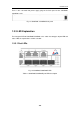
Installation Guide There is one 110~230V AC power supply plug on the back panel of the SS2GR50i/ SS2GR26i series. Fig 1-3 SS2GR50i / SS2GR26i back panel 1.3.3 LED Explanation The front panel LED of SS2GR50i/SS2GR26i series switch has two types of port LED and status LED, the explanation is shown as below: 1.3.3.1 Port LEDs Fig 1-4 SS2GR26I/SS2GR26IP LED Table1.
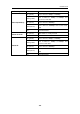
Installation Guide Panel Symbol Status On (yellow) Blink (yellow) Port1-24(Link/Act) On (Green) Blink (Green) Port21/22/23/24 Port is linked as 10Mbps or 100Mbps Port is linked as 10Mbps or 100Mbps and receives/sends data Port is linked as 1000Mbps Port is linked as 1000Mbps and receives/sends data Off Port linked failure On (Green) SFP module is exactly inserted Off SFP module is not inserted On (yellow) Port is linked as 10Mbps or 100Mbps Blink (yellow) Port25/26 Description On (Green) B
Installation Guide Fig 1-5 SS2GR50i LED Table1.
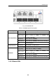
Installation Guide Fig 1-6 SS2GR26IP LED Table1.3 SS2GR50i/26i series LED description LED Power Diag Status Description On Power ok Off No power or failure Blink (Yellow) Diag result with failure in system On (Green) Diagnosis successfully finished On (Yellow) System is initializing diagnosis Blink(Yellow, Green) Boot is initializing 1.3.4 Front Panel Port Description The front ports of SS2GR50I/26I series, are shown below and described in the following table.
Installation Guide 9/125um single mode fiber: 40km z MGBS-GLX70, SFP-LH-70-L transceiver: 9/125um single mode fiber: 70km z MGBS-GLX120, SFP-LH-120-L transceiver: 9/125um single mode fiber: 120km 1-8
Installation Guide Chapter 2 Hardware Installation 2.1 Installation Notice To ensure the proper operation of SS2GR50i/26i series and your physical security, please read carefully the following installation guide. 2.1.1 Environmental Requirements The switch must be installed in a clean area. Otherwise, the switch may be damaged by electrostatic adherence. Maintain the temperature within 0 to 50 °C and the humidity within 5% to 95%, non-condensing.
Installation Guide the threshold value. Gas Average (mg/m³) Max (mg/m³) SO2 0.2 1.5 H2S 0.006 0.03 NO2 0.04 0.15 NH3 0.05 0.15 Cl2 0.01 0.3 Table 2.2 Environmental Requirements: Particles 2.1.1.2 Temperature and Humidity Although the switch is designed to use 4 fans, the site should still maintain a desirable temperature and humidity.
Installation Guide air-conditioning system failure, and normal operation conditions should be recovered within 5 hours. 2.1.1.3 Power Supply The power input parameters for the switch is shown as below: AC input: 100~240VAC Frequency: 50~60H Before powering on the power supply, please check the power input to ensure proper grounding of the power supply system. The input source for the switch should be reliable and secure; a voltage adaptor can be used if necessary.
Installation Guide Provide electromagnetic shielding if necessary. 2.1.1.6 Rack Configuration The dimensions of the switch are designed to be mounted on a standard 19’’ rack, the dimensions are 440mm x 44mm x 410mm (W x H x D). Please ensure good ventilation for the rack. Every device in the rack will generate heat during operation, therefore vent and fans must be provided for an enclosed rack, and devices should not be stacked closely.
Installation Guide Do not touch the power plug and power socket. Do not place the tinder near the switch. Do not configure the switch alone in a dangerous situation, Use standard power sockets which have overload and leakage protection. Inspect and maintain the site and the switch regularly. Have the emergence power switch on the site. In case of emergence, switch off the power immediately. 2.2 Installation Preparation 2.2.
Installation Guide to the rack with the screws provided. Leave enough space around the switch for good air circulation. Fig 2-2 Rack-mounting the switch Caution The brackets are used to fix the switch on the rack. They can’t serve as a bearing. Please place a rack shelf under the switch. Do not place anything on top of the switch. Do not block the blowholes on the switch to ensure the proper operation of the switch. 2.3.
Installation Guide 3. Power on the switch and the character terminal. Configure the switch through the character terminal. 2.3.3 SFP Transceiver Installation SS2GR50i/26i series provides multiple 1000Mb SFP transceiver slots. The procedure for installing the SFP transceiver is shown below: Step 1: Put on a ESD wrist strap (or antistatic gloves) Step 2: Insert the SFP transceiver to the guide rail inside the fiber interface line card. Do not put the SFP transceiver up-side-down.
Installation Guide established; otherwise the link is not ready and should be examined. Caution Please verify the sign above the port to ensure using the other ports. Connecting to wrong ports might damage the transceiver or the other ports. When connecting other devices through a fiber cable to the switch, the output power of the fiber cable must not exceed the maximum received power of the corresponding modules. Otherwise, it will damage the switch.
Installation Guide ©Amer.com Corp. 1997-2007 All rights reserved.