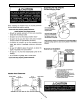
PRODUCT SPECIFICATIONS AND ENGINEERING INFORMATION ----SUBMITTAL DATA HRV 120SRD HEAT RECOVERY VENTILATOR # 28 051 THERMALLY CONDUCTIVE, PATENTED ALUMINUM CORE The cross-flow heat recovery core transfers heat between the two airstreams. It is easily removed for cleaning or service. MOTORS AND BLOWERS Each air stream has an independent motorized impeller. 3 speed operation 120VAC PERFORMANCE E.S.P. (in.wg.) CFM 0.1 143 0.2 138 0.3 132 0.4 128 0.5 123 0.6 116 0.7 113 0.8 106 0.9 103 1.0 97 Max.
Engineering Data Model HRV 120SRD 3
Clearances and Requirements The HRV unit must be installed in the positions as shown in the illustrations on page 6.
Installation 5
Hanging or Mounting the HRV 6
Duct Design and Installation Drain Connections 8
Partially Dedicated System 9
Simplified Installation 10
Fully Dedicated Installation 11
Optional Controls 12
Dehumidistat Operation (HRV only) Defrost Operation Defrost Cycle DIP Switch Settings 13
Operation Fan speed DIP Switch Settings Electrical 14
Wiring the Controls 15
Optional Controls Connecting the HRV as illustrated will ensure the Air Handler/Furnace Blower Motor is operating whenever the HRV is ventilating.
Air Flow Balancing 17
Pitot Tube and Gauge Air Flow Balancing Kit with c/w magnehelic gauge, 1 - 6" sensor, 1 - 8" sensor, airflow table, and carry case.
Troubleshooting 19
Maintenance 20
Wiring Diagrams HRV 120SRD Control Box 21
Notes _____________________________________________________________________________________________________________________________________________________________________________________ __________________________________________________________________________________________________________________________________________________________________________________ _______________________________________________________________________________________________________________________________________________
Maintenance Record Note: It is important to maintain this product regularly to ensure optimal performance.