
Operation Manual


TOR SWITCH (23)isinthe“PHONO”position.WhenCDplayers,TapeDecksandotherlinelevel
instrumentsareconnectedtothesejackstheCHANNEL LINE LEVEL SELECTOR SWITCH (21) is
inthe“LINE”position.Neverconnectlinelevelinstruments(CDplayers,tapedecks,etc.)tothese
jackswhentheCHANNEL LINE LEVEL SELECTOR SWITCH (21)isinthe“PHONO”position, THIS
MAY SERIOUSLY DAMAGE YOUR MIXER! TheredcoloredRCAjackrepresentstherightchannel
inputandthewhiterepresentstheleftchannelinput.Thechannel SOURCE SELECTOR SWITCH (1)
mustbeinthe“Analog”position,tomonitoranysourceconnectedtothesejacks.
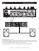
21. CHANNEL LINE LEVEL SELECTOR SWITCHES - Theseswitchesareusedtochangethevolt-
agelinelevelsofthererespectedPhono/LineRCAinputsjacks.Whenconnectingturntableswith
magneticcartridgestothesejacksbesurethecorrespondingswitchisinthe“PHONO”position,
andwhenusinglinelevelinputdevicesbesurethisswitchisinthe“LINE”position.Alwaysbesure
mainpowerisshutoffbeforechangethepositionoftheLineLevelSelectorSwitch.
22. CHANNEL 3: INPUTS - Thetypeofinputmustdirectlyreecttheselectedmodeofthe CHAN-
NEL LINE LEVEL SELECTOR SWITCH (21). CDplayers,TapeDecksandotherlinelevelinstruments
maybeconnectedtothesejacks.TheredcoloredRCAjackrepresentstherightchannelinputand
thewhiterepresentstheleftchannelinput.Inputvolumewillbecontrolledbychannelthree fader.
Thechannel SOURCE SELECTOR SWITCH (1) must be in the“Analog”position, to monitor any
sourceconnectedtothesejacks.TurntablesequippedwithMMpickupcartridge(AllDJturntable
useMMpick-upcartridges)maybeconnectedtothesejacksaslongastheCHANNEL LINE LEVEL
SELECTOR SWITCH (21)isinthe“PHONO”position.WhenCDplayers,TapeDecksandotherline
levelinstrumentsareconnectedtothesejackstheCHANNEL LINE LEVEL SELECTOR SWITCH (21)
isinthe“LINE”position.Neverconnectlinelevelinstruments(CDplayers,tapedecks,etc.)tothese
jackswhentheCHANNEL LINE LEVEL SELECTOR SWITCH (21)isinthe“PHONO”position, THIS
MAY SERIOUSLY DAMAGE YOUR MIXER! TheredcoloredRCAjackrepresentstherightchannel
inputandthewhiterepresentstheleftchannelinput.Thechannel SOURCE SELECTOR SWITCH (1)
mustbeinthe“Analog”position,tomonitoranysourceconnectedtothesejacks.
23. CHANNEL 4: LINE 4 INPUT JACKS - DO NOT CONNECT TURNTABLES TO THESE JACKS!
CDplayers,TapeDecksandotherlinelevelinstrumentsmaybeconnectedtothesejacks.Thered
coloredRCAjackrepresentstherightchannelinputandthewhiterepresentstheleftchannelinput.
Inputvolumewillbecontrolledbychannelonefader. Thechannel SOURCE SELECTOR SWITCH (1)
mustbeinthe“Analog”position,tomonitoranysourceconnectedtothesejacks.
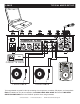
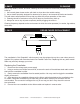
24. RCA MASTER OUTPUTS - TheMasterOutputincludesapair XLR BALANCED JACKS (26)
aswellasapairofRCA UnbalancedJacks.TheRCAjackssendalowcurrentunbalancedoutput
signal.Thesejacksshouldonlybeusedforshortercablerunstosignalprocessorsorloopingto
anothermixer.Forcablerunsgreaterthan15feetusethe XLR BALANCED JACKS (26).
25. BOOTH OUTPUTS -TheVMS4offersasecondaryoutputusuallyusedtomonitoryourmix
ortoroutetoanoutboardrecordingdevice.Thisoutputhasindependentvolumecontrol“Booth”
knob.
26. BALANCED XLR MASTER OUTPUT JACKS - The Master Output includes a pair of XLR
BalancedjacksaswellasapairofRCA UNBALANCED JACKS (24).The3-pinXLRjackssenda
highcurrentbalancedoutputsignal.Thesejacksshouldbeusedwhenyouwillbedrivinganampor
otheraudioequipmentwithabalancedinput,orwheneveryouwillberunningasignallinegreater
than15feet.Always,usethesejackswheneverpossible.
27. USB PORT -ConnecttoyourPCforMIDIinterfaceandUSBinterface(audioinandouts).
14MXR CONTROLS AND FUNCTIONS cont.
©American Audio® - www.americanaudio.us - 14MXR Instruction Manual Page 14