www.ti.com SLAS495A− JUNE 2006 − REVISED OCTOBER 2007 FEATURES D Stereo Audio DAC and Mono ADC Support D D D D D D D D D D Rates Up to 48kHz High Quality 95dB Stereo Audio Playback Performance Low Power 19−mW Stereo Audio Playback at 48kHz Sample Rate and 3.3V Analog Supply Level Programmable Digital Audio Effects/Bass/Treble/EQ/De−Emphasis Filters Programmable Gain Amplifiers MIC Preamp and Hardware Automatic Gain Control With Up to 59.
www.ti.com SLAS495A− JUNE 2006 − REVISED OCTOBER 2007 This integrated circuit can be damaged by ESD. Texas Instruments recommends that all integrated circuits be handled with appropriate precautions. Failure to observe proper handling and installation procedures can cause damage. ESD damage can range from subtle performance degradation to complete device failure.
www.ti.
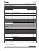
www.ti.com SLAS495A− JUNE 2006 − REVISED OCTOBER 2007 ABSOLUTE MAXIMUM RATINGS over operating free-air temperature range unless otherwise noted(1), (2) UNITS AVDD1/2 to AVSS1/2 −0.3 V to 3.9 V DRVDD to DRVSS1/2 −0.3 V to 3.9 V BVDD to DRVSS1/2 −0.3 V to 4.5 V IOVDD to DVSS −0.3 V to 3.9 V Digital input voltage to DVSS −0.3 V to IOVDD + 0.3 V Analog input (except VBAT) voltage to AVSS1/2 −0.3 V to AVDD + 0.3 V VBAT input voltage to AVSS1/2 −0.3 V to 6 V AVSS1/2 to DRVSS1/2 to DVSS −0.
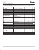
www.ti.com SLAS495A− JUNE 2006 − REVISED OCTOBER 2007 ELECTRICAL CHARACTERISTICS At +25°C, AVDD1, AVDD2, DRVDD, IOVDD = 3.3 V, BVDD = 3.9 V, DVDD = 1.8 V, Vref = 2.5 V, Fs (Audio) = 48 kHz, unless otherwise noted PARAMETER TEST CONDITIONS MIN TYP MAX UNITS TOUCH SCREEN − AUXILIARY ANALOG INPUT Input voltage range 0 Input capacitance AUX1/2 input selected as input by touch-screen Input leakage current +VREF V 25 pF 1 µA BATTERY MONITOR INPUTS Input voltage range 0.
www.ti.com SLAS495A− JUNE 2006 − REVISED OCTOBER 2007 ELECTRICAL CHARACTERISTICS (continued) At +25°C, AVDD1, AVDD2, DRVDD, IOVDD = 3.3 V, BVDD = 3.9 V, DVDD = 1.8 V, Int. Vref = 2.5 V, Fs (Audio) = 48 kHz, unless otherwise noted (continued) PARAMETER TEST CONDITIONS MIN TYP MAX UNITS HEADSET MICROPHONE BIAS Voltage range PSRR Sourcing current Register 1DH/Page 2, D7−D8=00 3.3 Register 1DH/Page 2, D7−D8=01 2.
www.ti.com SLAS495A− JUNE 2006 − REVISED OCTOBER 2007 ELECTRICAL CHARACTERISTICS (continued) At +25°C, AVDD1, AVDD2, DRVDD, IOVDD = 3.3 V, BVDD = 3.9 V, DVDD = 1.8 V, Vref = 2.5 V, Fs (Audio) = 48 kHz, unless otherwise noted (continued) PARAMETER DAC SPEAKER OUTPUT TEST CONDITIONS MIN Full-scale output voltage (0 dB) UNITS Vrms 1.75 SNR Measured as idle channel noise, A-weighted THD −1 dBFS Input, 0-dB gain Interchannel isolation MAX 1.
www.ti.com SLAS495A− JUNE 2006 − REVISED OCTOBER 2007 ELECTRICAL CHARACTERISTICS (continued) At +25°C, AVDD1, AVDD2, DRVDD, IOVDD = 3.3 V, BVDD = 3.9 V, DVDD = 1.8 V, Vref = 2.5 V, Fs (Audio) = 48 kHz, unless otherwise noted (continued) PARAMETER CP_INP TO 32Ω RECEIVER (SPK1−OUT32N) TEST CONDITIONS MIN TYP Full-scale input voltage (0 dB) UNITS 0.707 Input common mode Vrms 1.5 Full-scale output voltage (0 dB) V 1.
www.ti.com SLAS495A− JUNE 2006 − REVISED OCTOBER 2007 ELECTRICAL CHARACTERISTICS (continued) At +25°C, AVDD1, AVDD2, DRVDD, IOVDD = 3.3 V, BVDD = 3.9 V, DVDD = 1.8 V, Vref = 2.5 V, Fs (Audio) = 48 kHz, unless otherwise noted (continued) PARAMETER TEST CONDITIONS MIN TYP MAX UNITS POWER SUPPLY REQUIREMENTS Power supply voltage AVDD1, AVDD2 3 3.3 3.6 V DRVDD 3 3.3 3.
www.ti.com SLAS495A− JUNE 2006 − REVISED OCTOBER 2007 FUNCTIONAL BLOCK DIAGRAM AVDD1 Y+ X− X+ Y− Touch Panel Drivers VBAT Battery Monitor AVDD2 DRVDD BVDD DVDD IOVDD SCLK OSC Touch Screen Processing and SPI Interface SAR ADC Temperature Measurement VREF MICBIAS_HED MIC_DETECT_IN Internal Reference 2.0/2.5/3.3 To Detection block PINTDAV RESET 0 to 59.5dB (0.5dB steps) MICBIAS_HND AUX1 AUX2 MICIN_HED 0 to 59.5dB (0.5dB steps) 12 to −34.5dB (0.
www.ti.com SLAS495A− JUNE 2006 − REVISED OCTOBER 2007 SPI TIMING DIAGRAM /SS S SPISELZ S S SCLK S S SPISELZ S SPICLK MISO S E SPISELZ L t sck tLead t td tLag twsck tf tr twsck tv tho MSB OUT BIT 6 . . . 1 tdis LSB OUT ta MOSI SPISELZ tsu thi MSB IN BIT 6 . . . 1 LSB IN TYPICAL TIMING REQUIREMENTS All specifications typical at 25°C, DVDD = 1.8 V(1) PARAMETER IOVDD = 1.1 V MIN MAX IOVDD = 3.
www.ti.com SLAS495A− JUNE 2006 − REVISED OCTOBER 2007 AUDIO INTERFACE TIMING DIAGRAMS WCLK td(WS) BCLK td(DO−WS) td(DO−BCLK) SDOUT th(DI) ts(DI) SDIN Figure 1. I2S/LJ/RJ in Master Mode Typical Timing Requirements (see Figure 1) IOVDD = 1.1 V PARAMETER(1) td(WS) td(DO−WS) MIN MIN MAX UNITS WCLK delay 30 15 ns WCLK to DOUT delay (for LJF mode) 30 15 ns 30 15 ns td(DO−BCLK) BCLK to DOUT delay ts(DI) SDIN setup th(DI) tr MAX IOVDD = 3.
www.ti.com SLAS495A− JUNE 2006 − REVISED OCTOBER 2007 WCLK th(WS) BCLK tL(BCLK) tH(BCLK) ts(WS) td(DO−WS) td(DO−BCLK) tP(BCLK) SDOUT th(DI) ts(DI) SDIN Figure 3. I2S/LJF/RJF Timing in Slave Mode Typical Timing Requirements (see Figure 3) PARAMETER(1) IOVDD = 1.1 V MIN MAX IOVDD = 3.
www.ti.com SLAS495A− JUNE 2006 − REVISED OCTOBER 2007 WCLK th(WS) BCLK ts(WS) th(WS) tL(BCLK) tH(BCLK) ts(WS) td(DO−BCLK) tP(BCLK) SDOUT th(DI) ts(DI) SDIN Figure 4. DSP Timing in Slave Mode Typical Timing Requirements (see Figure 4) PARAMETER(1) IOVDD = 1.1 V MIN MAX IOVDD = 3.
www.ti.com SLAS495A− JUNE 2006 − REVISED OCTOBER 2007 TYPICAL CHARACTERISTICS 1.5 AVDD1/AVDD2 = 3.3 V, TA = 25 C, IR = 2.5 V 1 LSB 0.5 0 −0.5 −1 −1.5 500 0 1000 1500 2000 CODE 2500 3000 3500 4000 Figure 5. SAR INL (TA = 25 C, Internal Reference = 2.5 V, 12 bit, AVDD1/AVDD2 = 3.3 V) 1 AVDD1/AVDD2 = 3.3 V, TA = 25 C, IR = 2.5 V LSB 0.5 0 −0.5 −1 0 500 1000 1500 2000 CODE 2500 3000 3500 4000 Figure 6. SAR DNL (TA = 25 C, Internal Reference = 2.5 V, 12 bit, AVDD1/AVDD2 = 3.
www.ti.com SLAS495A− JUNE 2006 − REVISED OCTOBER 2007 0 AVDD1/AVDD2 = 3.3 V, TA = 25 C, −20 −40 dB −60 −80 −100 −120 −140 −160 500 0 1000 1500 2000 2500 3000 3500 4000 f − Frequency − Hz Figure 8. ADC FFT Plot at 8 ksps (TA = 25 C, −1 dB, 1 kHz input, AVDD1/AVDD2 = 3.3 V) 0 AVDD1/AVDD2 = 3.3 V, TA = 25 C, −20 −40 dB −60 −80 −100 −120 −140 −160 5000 0 10000 15000 f − Frequency − Hz 20000 Figure 9. ADC FFT Plot at 48 ksps (TA = 25 C, −1 dB, 1 kHz input, AVDD1/AVDD2 = 3.
www.ti.com SLAS495A− JUNE 2006 − REVISED OCTOBER 2007 20 AVDD1/AVDD2 = 3.3 V, TA = 25 C, RL = 16 W 0 −20 dB −40 −60 −80 −100 −120 −140 −160 0 5000 10000 15000 20000 f − Frequency − Hz Figure 11. DAC FFT Plot (TA = 25 C, −1 dB, 1 kHz Input, AVDD1/AVDD2/DRVDD = 3.3 V, RL = 16 Ω) THD − Total Hormonic Distortion − dB −77 AVDD1/AVDD2 = 3.3 V, TA = 25 C, RL = 16 W −78 −79 −80 −81 −82 −83 −84 5 10 15 20 25 30 Power − mW 35 40 45 Figure 12.
www.ti.com SLAS495A− JUNE 2006 − REVISED OCTOBER 2007 THD − Total Hormonic Distortion − dB −60 AVDD1/AVDD2/DRDD = 3.3 V, BVDD = 3.9 V TA = 25 C, RL = 8 W −65 −70 −75 −80 −85 −90 0 50 100 150 200 250 300 350 400 Power − mW Figure 13. THD vs Power on Loudspeaker Driver (TA = 25 C, 1 kHz Input, AVDD1/AVDD2/DRVDD = 3.3 V, BVDD = 3.9 V, RL = 8 Ω) 450 Max Power Output − mW 400 350 300 250 200 150 2.7 2.9 3.1 3.3 3.5 3.7 BVDD − V 3.9 4.1 Figure 14.
www.ti.com SLAS495A− JUNE 2006 − REVISED OCTOBER 2007 OVERVIEW The TSC2111 is a highly integrated stereo audio DAC and mono audio ADC with touch screen controller for portable computing, communication and entertainment applications. A register-based architecture eases integration with microprocessor-based systems through a standard SPI bus. All peripheral functions are controlled through the registers and on-board state machines.
www.ti.com SLAS495A− JUNE 2006 − REVISED OCTOBER 2007 D Word Select Signals The word select signal (WCLK) indicates the channel being transmitted: — WCLK = 0: left channel for I2S mode; — WCLK = 1: right channel for I2S mode. For other modes refer to the timing diagrams below. D Bitclock (BCLK) Signal In addition to being programmable as master or slave mode, the BCLK can also be configured in two transfer modes, 256-S transfer mode and continuous transfer mode, which are described below.
www.ti.com SLAS495A− JUNE 2006 − REVISED OCTOBER 2007 D Left Justified Mode In left-justified mode, the MSB of right channel is valid on the rising edge of BCLK, following the falling edge on WCLK. Similarly the MSB of left channel is valid on the rising edge of BCLK following the rising edge of WCLK. 1/fs WCLK BCLK Left Channel SDIN/ SDOUT n−1 n−2 n−3 2 Right Channel 1 MSB 0 n−1 n−2 n−3 2 1 0 n n−1 LSB Figure 16.
www.ti.com SLAS495A− JUNE 2006 − REVISED OCTOBER 2007 AUDIO DATA CONVERTERS The TSC2111 includes a stereo audio DAC and a mono audio ADC. Both ADC and DAC can operate with a maximum sampling rate of 53 kHz and support all audio standard rates of 8 kHz, 11.025 kHz, 12 kHz, 16 kHz, 22.05 kHz, 24 kHz, 32 kHz, 44.1 kHz, and 48 kHz.
www.ti.com SLAS495A− JUNE 2006 − REVISED OCTOBER 2007 D When PLL is enabled Fsref + MCLK 2048 K P P = 1, 2, 3 … 8 K = J.D J = 1, 2, 3 ….63 D = 0, 1, 2 … 9999 P, J and D are register programmable. where J is integer part of K before the decimal point, and D is four-digit fractional part of K after the decimal point, including lagging zeros. Examples: If K = 8.5, then J = 8, D = 5000 If K = 7.12, then J = 7, D = 1200 If K = 7.
www.ti.com SLAS495A− JUNE 2006 − REVISED OCTOBER 2007 Table 2. Fsref = 48 kHz MCLK (MHz) P J D ACHIEVED FSREF % ERROR 2.048 1 48 0 48000.00 0.0000 3.072 1 32 0 48000.00 0.0000 4.096 1 24 0 48000.00 0.0000 6.144 1 16 0 48000.00 0.0000 8.192 1 12 0 48000.00 0.0000 12.0 1 8 1920 48000.00 0.0000 13.0 1 7 5618 47999.71 −0.0006 16.0 1 6 1440 48000.00 0.0000 19.2 1 5 1200 48000.00 0.0000 19.68 1 4 9951 47999.79 −0.0004 48.
www.ti.com SLAS495A− JUNE 2006 − REVISED OCTOBER 2007 upon power down, the PGA soft-steps the volume to mute before shutting down. A read−only flag (D7 control register 1FH/Page 2) is set whenever the gain applied by PGA equals the desired value set by the register. The soft-stepping control can be disabled by the programming D12=1 in register 1DH of Page 2.
www.ti.com SLAS495A− JUNE 2006 − REVISED OCTOBER 2007 See Table 3 for various AGC programming options. AGC can be used only if microphone input or Cell-phone input is routed to the ADC channel. When both microphone input and Cell-phone input are connected to the ADC, AGC is automatically disabled. Input Signal Target Gain Output Signal AGC Gain Attack Time Decay Time Figure 19. AGC Characteristics Table 3.
www.ti.com SLAS495A− JUNE 2006 − REVISED OCTOBER 2007 Stereo Audio DAC Each channel of the stereo audio DAC consists of a digital audio processing block, a digital interpolation filter, digital delta-sigma modulator, and an analog reconstruction filter.
www.ti.com SLAS495A− JUNE 2006 − REVISED OCTOBER 2007 Delta-Sigma DAC The audio digital-to-analog converter incorporates a third order multi-bit delta-sigma modulator followed by an analog reconstruction filter. The DAC provides high-resolution, low−noise performance, using oversampling and noise shaping techniques. The analog reconstruction filter design consists of a 6 tap analog FIR filter followed by a continuous time RC filter. The analog FIR operates at 6.
www.ti.com SLAS495A− JUNE 2006 − REVISED OCTOBER 2007 DAC Powerdown The DAC powerdown flag (D4D3 of control register 05H/page 2) along with D10 of control register 05H/page 2 denotes the powerdown status of the DAC according to Table 4. Table 4. DAC Powerdown Status D10, D4, D3 POWERUP/POWERDOWN STATE OF DAC 0,0,0 DAC left and right are in stable powerup state. 0,0,1 DAC left is in stable powerup state. DAC right is in the process of powering up.
www.ti.com SLAS495A− JUNE 2006 − REVISED OCTOBER 2007 0 −2 −4 Gain − dB −6 −8 −10 −12 −14 −16 −18 −20 0 200 400 600 f − Frequency − Hz 800 1000 Figure 20. Uncompensated Response For 16-Ω Load and 50-mF Decoupling Capacitor 0 −2 −4 Gain − dB −6 −8 −10 −12 −14 −16 −18 −20 0 200 400 600 f − Frequency − Hz 800 1000 Figure 21.
www.ti.com SLAS495A− JUNE 2006 − REVISED OCTOBER 2007 For the cap interface, this feature can be disabled by setting bit D0 of control register 20H/page 2. In the case of the cap-less interface, VGND short circuit protection must also be disabled, which can be achieved by setting bit D4 of control register 21H/page 2. The TSC2111 implements a pop reduction scheme to reduce audible artifacts during powerup and powerdown of headphone drivers.
www.ti.com SLAS495A− JUNE 2006 − REVISED OCTOBER 2007 MICBIAS_HND 2.5 MICIN_HND OUT8P LOUDSPEAKER OUT8N MICBIAS_HED MIC_DETECT_IN Stereo Cellular g g s m s m To Detection block s RECEIVER g 3.3V MICIN_HED OUT32N Stereo + Cellular −1 s s −1 SPK1 SPK2 m = mic s = stere g = ground/midbias SPKFC VGND Figure 22. Connection Diagram for Capless Interface D Cap Interface Figure 23 shows connection diagram to device for cap interface. 32 To Detection block 1.
www.ti.com SLAS495A− JUNE 2006 − REVISED OCTOBER 2007 MICBIAS_HND 2.5V MICIN_HND OUT8P LOUDSPEAKER OUT8N MICBIAS_HED MIC_DETECT_IN Stereo Cellular g g s m s g m 2.5V To Detection block MICIN_HED s RECEIVER Stereo + Cellular −1 s s m = mic s = stere g = ground/midbias OUT32N −1 SPK1 SPK2 SPKFC VGND To Detection block 1.5 V Figure 23.
www.ti.com SLAS495A− JUNE 2006 − REVISED OCTOBER 2007 s s s g g g s s m m Stereo + Cellular g m s s Cellular g m s Stereo g s s Figure 24. Connection Diagram for Jacks D Headset Detection − Interrupt polarity: Active high. − Typical interrupt duration: 1.75 ms.
www.ti.com SLAS495A− JUNE 2006 − REVISED OCTOBER 2007 Differential Smart Phone Interface The TSC2111 provides a pin−compatible upgrade to TSC2101. One improvement is the ability to connect differentially to a cell phone module, which improves noise immunity in the customers system. When configured as differential input (bit D10, Register 06h, page 2) the CP_INP pin and BUZZ_IN/CP_INN pin function as a differential input to the CP_INP PGA.
www.ti.com SLAS495A− JUNE 2006 − REVISED OCTOBER 2007 Conductive Bar Transparent Conductor (ITO) Bottom Side Y+ X+ Transparent Conductor (ITO) Top Side X− Silver Ink Y− Insulating Material (Glass) ITO= Indium Tin Oxide Figure 25. 4-Wire Touch Screen Construction The 4-wire touch screen panel works by applying a voltage across the vertical or horizontal resistive network. The ADC converts the voltage measured at the point the panel is touched.
www.ti.com SLAS495A− JUNE 2006 − REVISED OCTOBER 2007 pressed. This settling time must be accounted for, or else the converted value will be in error. Therefore, a delay must be introduced between the time the driver for a particular measurement is turned on, and the time measurement is made. In some applications, external capacitors may be required across the touch screen for filtering noise picked up by the touch screen, i.e., noise generated by the LCD panel or back-light circuitry.
www.ti.com SLAS495A− JUNE 2006 − REVISED OCTOBER 2007 PINTDAV AVDD1 VREF VREF X+ X− REFP Y+ Y− IN+ CONVERTER IN− REFM VBAT AUX1 AUX2 AVSS1 Figure 27. Simplified Diagram of the Analog Input Section Data Format The TSC2111 output data is in unsigned Binary format and can be read from registers over the SPI interface. Reference The TSC2111 has an internal voltage reference that can be set to 1.25 V or 2.5 V, through the reference control register.
www.ti.com SLAS495A− JUNE 2006 − REVISED OCTOBER 2007 Variable Resolution The TSC2111 provides three different resolutions for the ADC: 8, 10 or 12 bits. Lower resolutions are often practical for measurements such as touch pressure. Performing the conversions at lower resolution reduce the amount of time it takes for the ADC to complete its conversion process, which lowers power consumption.
www.ti.com SLAS495A− JUNE 2006 − REVISED OCTOBER 2007 AVDD1 DATAV PINTDAV 50 kΩ TEMP1 Y+ TEMP2 HIGH EXCEPT WHEN TEMP1. TEMP2 ACTIVATED TEMP DIODE X+ Y− ON Y+ or X+ DRIVERS ON OR TEMP1 , TEMP2 MEASUREMENTS ACTIVATED Figure 28. PINTDAV Functional Block Diagram In modes where the TSC2111 needs to detect if the screen is still touched (for example, when doing a PINTDAV initiated X, Y, and Z conversion), the TSC2111 must reset the drivers so that the 50 KΩ resistor is connected.
www.ti.com SLAS495A− JUNE 2006 − REVISED OCTOBER 2007 Table 6. Programmable PINTDAV Functionality D15−D14 PINTDAV FUNCTION 00 Acts as PEN interrupt (active low) only. When PEN touch is detected, PINTDAV goes low. 01 Acts as data available (active low) only. The PINTDAV goes low as soon as one set of ADC conversions are completed for data of X,Y, XYZ, battery input, or auxiliary input selected by D13−D10 in control register 00H/Page 1.
www.ti.com SLAS495A− JUNE 2006 − REVISED OCTOBER 2007 Temperature Measurement In some applications, such as battery charging, a measurement of ambient temperature is required. The temperature measurement technique used in the TSC2111 relies on the characteristics of a semiconductor junction operating at a fixed current level. The forward diode voltage (VBE) has a well-defined characteristic versus temperature.
www.ti.com SLAS495A− JUNE 2006 − REVISED OCTOBER 2007 0.20 Error in Measurement − °C 0 −0.20 −0.40 −0.60 −0.80 −1 −1.20 −40 −20 0 20 40 60 TA − Free-Air Temperature − C 80 100 Figure 31. Typical Plot of Single Measurement Method After Calibrating for Offset and Gain At Two Temperatures The second mode uses a two-measurement (differential) method. This mode requires a second conversion with a current 82 times larger.
www.ti.com SLAS495A− JUNE 2006 − REVISED OCTOBER 2007 4 Error in Measurement − °C 3 2 1 0 −1 −2 −3 −4 −40 −20 0 20 40 60 TA − Free-Air Temperature − C 80 100 Figure 32. Typical Plot of Differential Measurement Method After Calibrating for Offset at Room Temperature The TSC2111 supports programmable auto-temperature measurement mode, which can be enabled using control register 0CH/page 1. In this mode, the TSC2111 can auto-start the temperature measurement after a programmable interval.
www.ti.com SLAS495A− JUNE 2006 − REVISED OCTOBER 2007 LDO or DC-DC Converter Battery 0.5 to 6 V 3.0 V to 3.6 V + − VDD R VBAT ADC 8 kΩ 2 kΩ Figure 33. Battery Measurement Functional Block Diagram Battery measurement can only be done in host−controlled mode. See the section Conversion Time Calculation for the TSC2111 and subsection Non Touch Measurement Operation in this data sheet for timing diagrams and conversion time calculations.
www.ti.com SLAS495A− JUNE 2006 − REVISED OCTOBER 2007 Where: VREF is the SAR ADC reference Vsar is input to the SAR ADC The TSC2111 supports programmable auto−auxiliary measurement mode, which can be enabled using control register 0CH/page 1. In this mode, the TSC2111 can auto start the auxiliary measurement after a programmable interval. The user can program minimum and maximum threshold values through a register.
www.ti.com SLAS495A− JUNE 2006 − REVISED OCTOBER 2007 converted data is going to be written. The trigger pointer indicates the location at which an interrupt will be generated if the write pointer reaches that location. Trigger level is the number of the data points needed to be present in the FIFO before generating an interrupt. For e.g., X−Y continuous scan mode with trigger level set to 8, the TSC2111 generates interrupt after writing (X1, Y1), (X2, Y2), (X3, Y3), (X4, Y4) i.e.
www.ti.com SLAS495A− JUNE 2006 − REVISED OCTOBER 2007 A transmission begins when initiated by a master SPI. The byte from the master SPI begins shifting in on the slave MOSI pin under the control of the master serial clock. As the byte shifts in on the MOSI pin, a byte shifts out on the MISO pin to the master shift register. The idle state of the serial clock for the TSC2111 is low, which corresponds to a clock polarity setting of 0 (typical microprocessor SPI control bit CPOL = 0).
www.ti.com SLAS495A− JUNE 2006 − REVISED OCTOBER 2007 Figure 36. TSC2111 Command Word SS SCLK MOSI COMMAND WORD DATA DATA Figure 37. Register Write Operation SS SCLK MOSI COMMAND WORD MOSO DATA DATA Figure 38. Register Read Operation TSC2111 Memory Map The TSC2111 has several 16-bit registers which allow control of the device as well as providing a location for results from the TSC2111 to be stored until read by the host microprocessor.
www.ti.
www.ti.com SLAS495A− JUNE 2006 − REVISED OCTOBER 2007 Bit 15 MSB Bit 14 Bit 13 Bit 12 Bit 11 Bit 10 Bit 9 Bit 8 Bit 7 Bit 6 Bit 5 Bit 4 Bit 3 Bit 2 Bit 1 Bit 0 LSB 0 0 0 0 R11 MSB R10 R9 R8 R7 R6 R5 R4 R3 R2 R1 R0 LSB PAGE 1 CONTROL REGISTER MAP REGISTER 00H: Touch-Screen ADC Control BIT NAME RESET VALUE READ/ WRITE D15 PSTCM 0 R/W Pen Status/Control Mode. READ 0 => There is no screen touch (default).
www.ti.com SLAS495A− JUNE 2006 − REVISED OCTOBER 2007 BIT NAME RESET VALUE READ/ WRITE D7−D6 ADAVG 00 R/W FUNCTION Converter Averaging Control. These two bits allow user to specify the number of averages the converter will perform selected by bit D0, which selects either Mean Filter or Median Filter.
www.ti.com SLAS495A− JUNE 2006 − REVISED OCTOBER 2007 BIT NAME RESET VALUE READ/ WRITE D10 XSTAT 0 R FUNCTION X Data Register Status 0 => No new data is available in X−data register 1 => New data for X−coordinate is available in register Note: This bit gets cleared only after the converted data of X coordinate has been completely read out of the register. This bit is not valid in case of buffer mode.
www.ti.com SLAS495A− JUNE 2006 − REVISED OCTOBER 2007 REGISTER 02H: Buffer Control BIT NAME RESET VALUE READ/ WRITE D15 BUFRES 0 R/W Buffer Reset. 0 => Buffer mode is disabled and RDPTR, WRPTR & TGPTR set to their reset value. 1 => Buffer mode is enabled. D14 BUFCONT 0 R/W Buffer Mode Selection 0 => Continuous conversion mode. 1 => Single shot mode.
www.ti.com SLAS495A− JUNE 2006 − REVISED OCTOBER 2007 REGISTER 04H: Reset Control BIT NAME RESET VALUE READ/ WRITE D15−D0 RSALL R/W FFFFH FUNCTION Reset All. Writing the code 0xBB00, as shown below, to this register causes the TSC2111 to reset all its control registers to their default, power−up values. 1011101100000000 => Reset all control registers Others => Do not write other sequences to the register.
www.ti.com SLAS495A− JUNE 2006 − REVISED OCTOBER 2007 REGISTER 07H: Temperature Min Threshold Measurement BIT NAME D15−D13 RESET VALUE READ/ WRITE FUNCTION 0’s R D12 TMNES 0 R/W Reserved Min Temperature (TEMP1 or TEMP2) threshold check enable for Auto/Non−Auto−Scan Measurement. 0 => Min Temperature threshold check is disabled. 1 => Min Temperature threshold check is enabled. Only valid for TEMP1 or TEMP2.
www.ti.com SLAS495A− JUNE 2006 − REVISED OCTOBER 2007 REGISTER 0CH: Measurement Configuration BIT NAME RESET VALUE READ/ WRITE D15 TSCAN 0 R/W TEMP Configuration when Auto−Temperature is selected 0 => TEMP1 is used for auto−temperature function 1 => TEMP2 is used for auto−temperature function D15 A1CONF 0 R/W AUX1 Configuration. 0 => AUX1 is used for voltage measurement. 1 => AUX1 is used for resistance measurement. D14 A2CONF 0 R/W AUX2 Configuration.
www.ti.com SLAS495A− JUNE 2006 − REVISED OCTOBER 2007 REGISTER 0DH: Programmable Delay In-Between Continuous Conversion BIT NAME D15 NTSPDELE N D14−D12 NTSPDINTV RESET VALUE READ/ WRITE 0 R/W Programmable delay for non−touch screen auto measurement mode 0 => Programmable delay is disabled for non−touch screen auto measurement mode. 1 => Programmable delay is enabled for non−touch screen auto measurement mode.
www.ti.com SLAS495A− JUNE 2006 − REVISED OCTOBER 2007 PAGE 2 CONTROL REGISTER MAP REGISTER 00H: Audio Control 1 BIT NAME RESET VALUE READ/ WRITE D15−D14 ADCHPF 00 R/W D13−D12 FUNCTION ADC High Pass Filter 00 => Disabled 01 => −3db point = 0.0045xFs 10 => −3dB point = 0.0125xFs 11 => −3dB point = 0.
www.ti.com SLAS495A− JUNE 2006 − REVISED OCTOBER 2007 REGISTER 01H: Gain Control for Headset/Aux Input BIT NAME RESET VALUE READ/ WRITE D15 ADMUT_HED 1 R/W Headset/Aux Input Mute 1 => Headset/Aux Input Mute 0 => Headset/Aux Input not muted Note: If AGC is enabled and Headset/Aux Input is selected then ADMUT_HED+ADPGA_HED reflects gain being applied by AGC. D14−D8 ADPGA_HED 1111111 R/W ADC Headset/Aux PGA Settings 0000000 => 0 dB 0000001 => 0.5 dB 0000010 => 1.0 dB ……… 1110110 => 59.
www.ti.com SLAS495A− JUNE 2006 − REVISED OCTOBER 2007 REGISTER 02H: CODEC DAC Gain Control BIT NAME RESET VALUE READ/ WRITE D15 DALMU 1 R/W DAC Left Channel Mute 1 => DAC Left Channel Muted 0 => DAC Left Channel not muted D14−D8 DALVL 1111111 R/W DAC Left Channel Volume Control 0000000 => DAC left channel volume = 0 dB 0000001 => DAC left channel volume = −0.5 dB ….. 1111110 => DAC left channel volume = −63.0 dB 1111111 => DAC left channel volume = −63.
www.ti.com SLAS495A− JUNE 2006 − REVISED OCTOBER 2007 REGISTER 04H: Audio Control 2 BIT NAME RESET VALUE READ/ WRITE D15 KCLEN 0 R/W Keyclick Enable 0 => Keyclick Disabled 1 => Keyclick Enabled Note: This bit is automatically cleared after giving out the keyclick signal length equal to the programmed value. D14−D12 KCLAC 100 R/W Keyclick Amplitude Control 000 => Lowest Amplitude …. 100 => Medium Amplitude ….
www.ti.com SLAS495A− JUNE 2006 − REVISED OCTOBER 2007 BIT NAME RESET VALUE READ/ WRITE D1 DASTC 0 R/W D0 ADGAF 0 R FUNCTION DAC Channel PGA Soft−stepping control 0 => 0.5 dB change every WCLK 1 => 0.5 dB change every 2 WCLK Headset/Aux or Handset PGA Flag 1 => Gain applied = PGA register setting. 0 => Gain applied ≠ PGA Register setting Note: This flag indicates when the soft−stepping for PGA is completed.
www.ti.com SLAS495A− JUNE 2006 − REVISED OCTOBER 2007 BIT NAME RESET VALUE READ/WRITE D1 EFFCTL 0 R/W Digital Audio Effects Filter 0 => Disable digital audio effects filter 1 => Enable digital audio effects filter FUNCTION D0 DEEMPF 0 R/W De−emphasis Filter Enable 0 => Disable de−emphasis filter 1 => Enable de−emphasis filter NOTE: D15−D6 are all 1’s, then full codec section is powered down.
www.ti.com SLAS495A− JUNE 2006 − REVISED OCTOBER 2007 REGISTER 08H: Digital Audio Effects Filter Coefficients BIT NAME RESET VALUE (IN DECIMAL) READ/ WRITE D15−D0 L_N1 −27034 R/W FUNCTION Left channel bass-boost coefficient N1. REGISTER 09H: Digital Audio Effects Filter Coefficients BIT NAME RESET VALUE (IN DECIMAL) READ/ WRITE D15−D0 L_N2 26461 R/W FUNCTION Left channel bass-boost coefficient N2.
www.ti.com SLAS495A− JUNE 2006 − REVISED OCTOBER 2007 REGISTER 14H: Digital Audio Effects Filter Coefficients BIT NAME RESET VALUE (IN DECIMAL) READ/ WRITE D15−D0 R_N3 27619 R/W FUNCTION Right channel bass-boost coefficient N3. REGISTER 15H: Digital Audio Effects Filter Coefficients BIT NAME RESET VALUE (IN DECIMAL) READ/ WRITE D15−D0 R_N4 −27034 R/W FUNCTION Right channel bass-boost coefficient N4.
www.ti.com SLAS495A− JUNE 2006 − REVISED OCTOBER 2007 REGISTER 1BH: PLL Programmability BIT NAME RESET VALUE READ/WRITE D15 PLLSEL 0 R/W PLL Enable 0 => Disable PLL. 1 => Enable PLL. D14−D11 QVAL 0010 R/W Q value: Valid when PLL is disabled 0000 => 16, 0001 => 17, 0010 => 2, 0011 => 3, …….
www.ti.
www.ti.com SLAS495A− JUNE 2006 − REVISED OCTOBER 2007 REGISTER 1EH: Gain Control for Handset Input BIT NAME RESET VALUE READ/WRITE D15 ADMUT_HND 1 R/W Handset Input Mute 1 => Handset Input Mute 0 => Handset Input not muted Note: If AGC is enabled and handset Input is selected then ADMUT_HND+ADPGA_HND will reflect gain being applied by AGC. FUNCTION D14−D8 ADPGA_HND 1111111 R/W D7−D5 AGCTG_HND 000 R/W ADC Handset PGA Settings 0000000 => 0 dB 0000001 => 0.5 dB 0000010 => 1.0 dB ....
www.ti.com SLAS495A− JUNE 2006 − REVISED OCTOBER 2007 REGISTER 1FH: Gain Control for Cell Phone Input and Buzzer Input BIT NAME RESET VALUE READ/WRITE D15 MUT_CP 1 R/W Cell phone Input PGA Power−down 1 => Power−down cell-phone input PGA 0 => Power−up cell phone input PGA FUNCTION D14−D8 CPGA 1000101 R/W Cell−phone Input PGA Settings. 0000000 => −34.5 dB 0000001 => −34 dB 0000010 => −33.5 dB ... 1000101 => 0 dB 1000110 => 0.5 dB ... 1011100 => 11.
www.ti.
www.ti.com SLAS495A− JUNE 2006 − REVISED OCTOBER 2007 REGISTER 21H: Audio Control 6 BIT NAME RESET VALUE READ/ WRITE D15 SPL2LSK 0 R/W Routing Selected for SPK1 Goes to OUT8P−OUT8N (Loudspeaker) Also. 0 => None of the routing selected for SPK1 goes to OUT8P−OUT8N. 1 => Routing selected for SPK1 using D14−D9 of control register 20H/page 2 goes to OUT8P−OUT8N. Note: This programming is valid only if SPK1/OUT32N and SPK2 are powered down.
www.ti.com SLAS495A− JUNE 2006 − REVISED OCTOBER 2007 REGISTER 22H: Audio Control 7 BIT NAME RESET VALUE READ/ WRITE D15 DETECT 0 R/W D14−D13 HESTYPE 00 R Type of Headset Detected. 00 => No headset detected. 01 => Stereo headset detected. 10 => Cellular headset detected 11 => Stereo+cellular headset detected Note: These two bits are valid only if the headset detection is enabled. D12 HDDETFL 0 R Headset Detection Flag. 0 => Headset is not detected 1 => Headset is detected.
www.ti.
www.ti.com SLAS495A− JUNE 2006 − REVISED OCTOBER 2007 REGISTER 24H: AGC for Cell-Phone Input Control BIT NAME D15 RESET VALUE READ/ WRITE FUNCTION 0 R Reserved (Write only 0) D14 AGCNF_CELL 0 R Noise Threshold Flag. The read values indicate the following 0 => Signal power greater than noise threshold 1 => Signal power is less than noise threshold Note: Valid only if AGC is selected for the Cell−phone input (CP_IN). D13−D11 AGCNL 000 R/W AGC Noise Threshold.
www.ti.com SLAS495A− JUNE 2006 − REVISED OCTOBER 2007 REGISTER 25H: Driver Power-Down Status Note: All values reflected in control register 25H/page2 are valid only if short circuit is not detected (bit D1 of control register 1DH/page2 is set to 0) BIT NAME RESET VALUE READ/ WRITE D15 SPK1FL 1 R SPK1 Driver Power-down Status 0 => SPK1 driver not powered down. 1 => SPK1 driver powered down. D14 SPK2FL 1 R SPK2 Driver Power-down Status 0 => SPK2 driver not powered down.
www.ti.com SLAS495A− JUNE 2006 − REVISED OCTOBER 2007 REGISTER 26H: Mic AGC Control BIT NAME RESET VALUE READ/ WRITE D15−D9 MMPGA 1111111 R/W Max PGA Value Applicable for Headset/Aux or Handset AGC 0000000 => 0 dB 0000001 => 0.5 dB 0000010 => 1.0 dB .... 1110110 => 59.0 dB ............ 1111111 => 59.5 dB D8−D6 MDEBNS 000 R/W Debounce Time for Transition from Normal Mode to Silence Mode (Input Level is Below Noise Threshold Programmed by AGCNL).
www.ti.com SLAS495A− JUNE 2006 − REVISED OCTOBER 2007 BIT NAME RESET VALUE READ/ WRITE D5−D3 CDEBSN 000 R De−bounce Time for Transition from Silence Mode to Normal Mode. This is Valid for Cell−phone AGC. 000 => 0 ms 001 => 0.5 ms 010 => 1.0 ms 011 => 2.0 ms 100 => 4.0 ms 101 => 8.0 ms 110 => 16.0 ms 111 => 32.
www.ti.com SLAS495A− JUNE 2006 − REVISED OCTOBER 2007 With this in mind, power to the TSC2111 should be clean and well bypassed. A 0.1 µF ceramic bypass capacitor should be placed as close to the device as possible. A 1 µF to 10 µF capacitor may also be needed if the impedance of the connection between the TSC2111 supply pins and system power supply is high. A 1 µF bypass capacitor should be placed on the VREF pin if the SAR ADC is intended to be used with the internal reference voltagel.
www.ti.
www.ti.
www.ti.
www.ti.
www.ti.
www.ti.
www.ti.com SLAS495A− JUNE 2006 − REVISED OCTOBER 2007 Port Scan Operation The time needed to complete one set of port scan conversions is given by: t coordinate +3 NJ ƪǒ N AVG N BITS Ǔ )1 ƫ Nj 8 MHz ) n ) 12 ) 1 1 ƒ conv t OSC ) 31 t OSC ) n2 where: n1 = 6 ; if ƒconv = 8 MHz 7 ; if ƒconv ≠ 8 MHz n2 = 0 ; if external reference mode is selected 3 ; if tREF = 0 µs or reference is programmed for power up all the time.
www.ti.com SLAS495A− JUNE 2006 − REVISED OCTOBER 2007 Figure 40. Frequency Response of ADC High-Pass Filter (Fcutoff = 0.0045 Fs) Figure 41. Frequency Response of ADC High-Pass Filter (Fcutoff = 0.
www.ti.com SLAS495A− JUNE 2006 − REVISED OCTOBER 2007 Figure 42. Frequency Response of ADC High-Pass Filter (Fcutoff = 0.025 Fs) DAC CHANNEL DIGITAL FILTER FREQUENCY RESPONSES Figure 43.
www.ti.com SLAS495A− JUNE 2006 − REVISED OCTOBER 2007 Figure 44. DAC Channel Digital Filter Pass-Band Frequency Response Figure 45.
www.ti.com SLAS495A− JUNE 2006 − REVISED OCTOBER 2007 Figure 46. De-Emphasis Filter Response at 32 Ksps Figure 47.
www.ti.com SLAS495A− JUNE 2006 − REVISED OCTOBER 2007 Figure 48. De-Emphasis Filter Frequency Response at 44.1 Ksps Figure 49. De-Emphasis Error at 44.
www.ti.com SLAS495A− JUNE 2006 − REVISED OCTOBER 2007 Figure 50. De-Emphasis Frequency Response at 48 Ksps Figure 51.
PACKAGE OPTION ADDENDUM www.ti.com 10-Jun-2014 PACKAGING INFORMATION Orderable Device Status (1) TSC2111IRGZT ACTIVE Package Type Package Pins Package Drawing Qty VQFN RGZ 48 250 Eco Plan Lead/Ball Finish MSL Peak Temp (2) (6) (3) Green (RoHS & no Sb/Br) CU NIPDAU Level-2-260C-1 YEAR Op Temp (°C) Device Marking (4/5) -40 to 85 TSC2111I (1) The marketing status values are defined as follows: ACTIVE: Product device recommended for new designs.
PACKAGE OPTION ADDENDUM www.ti.
PACKAGE MATERIALS INFORMATION www.ti.com 10-Mar-2014 TAPE AND REEL INFORMATION *All dimensions are nominal Device TSC2111IRGZT Package Package Pins Type Drawing VQFN RGZ 48 SPQ 250 Reel Reel A0 Diameter Width (mm) (mm) W1 (mm) 180.0 16.4 Pack Materials-Page 1 7.3 B0 (mm) K0 (mm) P1 (mm) W Pin1 (mm) Quadrant 7.3 1.5 12.0 16.
PACKAGE MATERIALS INFORMATION www.ti.com 10-Mar-2014 *All dimensions are nominal Device Package Type Package Drawing Pins SPQ Length (mm) Width (mm) Height (mm) TSC2111IRGZT VQFN RGZ 48 250 213.0 191.0 55.
IMPORTANT NOTICE Texas Instruments Incorporated and its subsidiaries (TI) reserve the right to make corrections, enhancements, improvements and other changes to its semiconductor products and services per JESD46, latest issue, and to discontinue any product or service per JESD48, latest issue. Buyers should obtain the latest relevant information before placing orders and should verify that such information is current and complete.