
Specifications


SLAS495A− JUNE 2006 − REVISED OCTOBER 2007
www.ti.com
26
See Table 3 for various AGC programming options. AGC can be used only if microphone input or Cell-phone
input is routed to the ADC channel. When both microphone input and Cell-phone input are connected to the
ADC, AGC is automatically disabled.
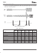
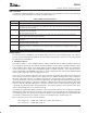
Decay Time
Target
Gain
Input
Signal
Output
Signal
AGC
Gain
Attack
Time
Figure 19. AGC Characteristics
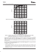
Table 3. AGC Settings
MIC HEADSET INPUT MIC HANDSET INPUT CELL-PHONE INPUT
BIT
CONTROL
REGISTER
BIT
CONTROL
REGISTER
BIT
CONTROL
REGISTER
AGC enable D0 01H D0 1EH D0 24H
Target gain D7−D5 01H D7−D5 1EH D7−D5 24H
Time constants (attack and decay time) D4−D1 01H D4−D1 1EH D4−D1 24H
Noise threshold D13−D11 24H D13−D11 24H D13−D11 24H
Noise threshold flag D11 04H D11 04H D14 24H
Hysteresis D10−D9 1DH D10−D9 1DH D10−D9 24H
Debounce time (normal to silence mode) D8−D6 26H D8−D6 26H D8−D6 27H
Debounce time (silence to normal mode) D5−D3 26H D5−D3 26H D5−D3 27H
Max PGA applicable D15−D9 26H D15−D9 26H D15−D9 27H
Gain applied by AGC D15−D8 01H D15−D8 1EH D14−D8 1FH
Saturation flag D0 04H D0 04H D7 1FH
Clip stepping disable D3 06H D3 06H D8 24H
NOTE
:
All settings shown in Table 3 are located in Page 2 of control registers.