
Manual


American Bicycle Security Company
P.O. Box 7359
Ventura, CA 93006
Ph: (800) 245-3723 or (805) 933-3688
Fax: (805) 933-1865
www.ameribike.com
Email: turtle@ameribike.com
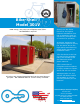
Bike-Shell™ Model 301V
ASSEMBLY INSTRUCTIONS 300 SERIES BICYCLE LOCKER
Your 300 series lockers (models 302, 301, 301P & 301V) do not require any general assembly.
Tools Needed:
Minimum requirements
3/8" electric drill (anchoring & installing diagonal divider wall)
3/8" electric rotary hammer drill (anchoring)
1/4" drill bit (anchoring & installing diagonal divider wall)
1/4" hammer drill bit (anchoring)
hammer (anchoring)
Tape measure - minimum 10' (anchoring & installing diagonal divider wall)
Extension cord 25' (anchoring & installing diagonal divider wall)
Generator or other source of power (anchoring & installing diagonal divider wall)
Safety glasses and any other equipment specified by the tool manufacturer. (All Steps)
-Choose location which allows a minimum 4' distance between door face and any obstruction to allow bicycle to
maneuver into locker and the door to swing open without hitting high spots such as concrete or asphalt raised by roots.
If desired, for grouping of units, chalk a line for straight edge with which to work. A preferred site would be concrete
although asphalt can be used. Site should be flat although it does not necessarily have to be level.
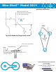
ANCHORING
The lockers should be anchored to the ground for optimum longevity and proper operation of the locking
system. Therefore, anchoring each unit to the ground is advisable. The 301 and 302 lockers are anchored in the 4
corners of the flange located around the inside of locker, the 301P, & 301V are anchored in the front two corners of the
locker and the rear. First square the doors in the frame. Out of square doors are due to the site being uneven. To
square the door, using a flat bar, raise the corner of the locker to make the door in square. If any adjustment is
necessary it should only be slight. Place a shim under the corner to retain the alignment and height. Shim should be
placed in a location under the base flange very close to hole for the anchor. This allows the downward force of the
anchor to be supported underneath and prevent cracking of the base flange at the anchor location. Drill through the
base flange on the locker with 1/4" drill. With hammer drill and 1/4" masonry bit you can then drill into concrete
surface. Drop the nail-in anchor through flange and into the hole, pound pin down flush with top of mushroom head of
anchor. Do this at all four corners of door frame on 301 & 302 lockers. On 301P and 301V do this in the front two
corners of the door frame and in center of rear wall.