ML-82 II (Gas - DSI/Steam Models) Installation Manual WARNING: For your safety the information in this manual must be followed to minimize the risk of fire or explosion or to prevent property damage, personal injury or death. AVERTISSEMENT: Assurez-vous de bien suivre les instructions données dans cette notice pour réduire au minimumle risque d’incendie ou d’explosion pour ou éviter tout dommage matériel, toute blessure ou la mort.
Retain This Manual In A Safe Place For Future Reference American Dryer Corporation products embody advanced concepts in engineering, design, and safety. If this product is properly maintained, it will provide many years of safe, efficient, and trouble-free operation. ONLY qualified technicians should service this equipment. OBSERVE ALL SAFETY PRECAUTIONS displayed on the equipment or specified in the installation manual included with the dryer.
IMPORTANT YOU MUST DISCONNECT AND LOCKOUT THE ELECTRIC SUPPLY AND THE GAS SUPPLY OR THE STEAM SUPPLY BEFORE ANY COVERS OR GUARDS ARE REMOVED FROM THE MACHINE TO ALLOW ACCESS FOR CLEANING, ADJUSTING, INSTALLATION, OR TESTING OF ANY EQUIPMENT PER OSHA (Occupational Safety and Health Administration) STANDARDS. “Caution: Label all wires prior to disconnection when servicing controls. Wiring errors can cause improper operation.
WARNING The dryer must never be operated with any of the back guards, outer tops, or service panels removed. PERSONAL INJURY OR FIRE COULD RESULT. WARNING DRYER MUST NEVER BE OPERATED WITHOUT THE LINT FILTER/SCREEN IN PLACE, EVEN IF AN EXTERNAL LINT COLLECTION SYSTEM IS USED. IMPORTANT PLEASE OBSERVE ALL SAFETY PRECAUTIONS displayed on the equipment and/or specified in the installation manual included with the dryer.
Table of Contents SECTION I IMPORTANT INFORMATION .......................................................................... 3 A. Receiving and Handling ............................................................................................................... 3 B. Safety Precautions ...................................................................................................................... 4 SECTION II SPECIFICATIONS/COMPONENT IDENTIFICATION .................................. 6 A.
SECTION VI ROUTINE MAINTENANCE ............................................................................ 37 A. B. C. D. Cleaning ................................................................................................................................... 37 Adjustments ............................................................................................................................. 38 Lubrication ...........................................................................................
SECTION I IMPORTANT INFORMATION A. RECEIVING AND HANDLING The dryer is shipped in a protective stretch wrap cover with protective cardboard corners and top cover (or optional box) as a means of preventing damage in transit. Upon delivery, the dryer and/or packaging, and wooden skid should be visually inspected for shipping damage. If any damage whatsoever is noticed, inspect further before delivering carrier leaves. Dryers damaged in shipment: 1.
B. SAFETY PRECAUTIONS WARNING: For your safety, the information in this manual must be followed to minimize the risk of fire or explosion or to prevent property damage, personal injury, or loss of life. WARNING: The dryer must never be operated with any of the back guards, outer tops, or service panels removed. PERSONAL INJURY OR FIRE COULD RESULT. 1. DO NOT store or use gasoline or other flammable vapors and liquids in the vicinity of this or any other appliance. 2.
WARNING: DO NOT dry mop heads. Contamination by wax or flammable solvents will create a fire hazard. WARNING: DO NOT use heat for drying articles that contain plastic, foam, sponge rubber, or similarly textured rubber materials. Drying in a heated basket (tumbler) may damage plastics or rubber and also may be a fire hazard. 7. A program should be established for the inspection and cleaning of lint in the burner area, exhaust ductwork, and area around the back of the dryer.
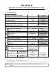
SECTION II SPECIFICATIONS/COMPONENT IDENTIFICATION A. SPECIFICATIONS BASKET (TUMBLER) DIAMETER BASKET (TUMBLER) DEPTH BASKET (TUMBLER) MOTOR BLOWER MOTOR DOOR OPENING (DIAMETER) BASKET (TUMBLER) VOLUME DRYERS PER 20'/40' CONTAINER DRYERS PER 45'/48' TRUCK VOLTAGE AVAILABLE APPROX. NET WEIGHT APPROX. SHIPPING WEIGHT HEAT INPUT AIRFLOW INLET PIPE CONNECTION* VOLTAGE AVAILABLE APPROX. NET WEIGHT APPROX. SHIPPING WEIGHT AIRFLOW COMPRESSED AIR VOLUME COMPRESSED AIR CONNECTION 37” 36” 1/2 HP 3 HP 31-3/8” 22.
Specifications ML-82 II (Gas and Steam ONLY) NOTE: ADC reserves the right to make changes in specifications at any time without notice or obligation.
B. COMPONENT IDENTIFICATION 1. Dryer Front View Illus. No.
2. Dryer Rear View Illus. No. 1 2 3* 4 5 6 7 8 9 * Description Heating Unit 1/8-inch Compressed Air Supply Inlet (behind electric service relay box for steam units only) Electric Service Relay Box Basket (tumbler) Bearing Mount Assembly Idler Bearing Mount Assembly Blower Motor Assembly Leveling Leg (rear) Basket (drive) Motor Assembly (reversing models only) Dryer Exhaust Electric service connections for gas models and steam models are made in this box.
SECTION III INSTALLATION PROCEDURES Installation should be performed by competent technicians in accordance with local and state codes. In the absence of these codes, the installation must conform to applicable American National Standards: ANSI Z223.1LATEST EDITION (National Fuel Gas Code) or ANSI/NFPA NO. 70-LATEST EDITION (National Electrical Code) or in Canada, the installation must conform to applicable Canadian Standards: CAN/CGA-B149.1-M91 (Natural Gas) or CAN/CGA-B149.2-M91 (Liquid Propane [L.P.
10. The dryer must be installed with provisions for adequate combustion and make-up air supply. CAUTION: This dryer produces combustible lint and must be exhausted to the outdoors. Every 6 months, inspect the exhaust ducting and remove any lint build up. B. UNPACKING/SETTING UP Remove protective shipping material (i.e., plastic wrap and optional shipping box) from dryer. IMPORTANT: Dryer must be transported and handled in an upright position at ALL times.
2. Leveling Dryer The dryer is equipped with four (4) leveling legs, one (1) at each corner of the dryer base. Two (2) are located at the rear of the dryer base, and two (2) are located in the lint chamber. To increase bearing life and improve efficiency, the dryer should be tilted slightly to the rear. C. DRYER ENCLOSURE REQUIREMENTS Bulkheads and partitions should be made of noncombustible materials and must be located a minimum of 12-inches (30.48 cm), 18-inches (45.
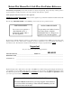
NOTE: Allowances must be made for opening the control door. Dryers may be positioned sidewall to sidewall. However, a 1/16-inch (1.5875 mm) minimum allowance must be made for opening and closing of the control door and the lint door. It is suggested that the dryer be positioned about 2 feet (0.61 meters) away from the nearest obstruction for ease of installation, maintenance, and service (to be measured from the back guard). Refer to the illustration above for details.
To compensate for the use of registers or louvers used over the openings, this make-up air must be increased by approximately thirty-three percent (33%). Make-up air openings should not be located in an area directly near where exhaust vents exit the building. It is not necessary to have separate make-up air openings for each dryer. Common make-up air openings are acceptable. However, they must be set up in such a manner that the make-up air is distributed equally to ALL the dryers.
E. EXHAUST REQUIREMENTS 1. General Exhaust Ductwork Information Exhaust ductwork should be designed and installed by a qualified professional. Improperly sized ductwork will create excessive back pressure which results in slow drying, increased use of energy, overheating of the dryer, and shut down of the burner by the airflow (sail) switches, burner hi-limits, or basket (tumbler) hi-heat thermostats. The dryer must be installed with a proper exhaust duct connection to the outside.
IMPORTANT: Exhaust back pressure measured by a manometer in the exhaust duct must be no less than 0 and must not exceed 0.3 inches (0.74 mb) of water column (W.C.). NOTE: When the exhaust ductwork passes through a wall, ceiling, or roof made of combustible materials, the opening must be 2-inches (5.08 cm) larger than the duct (all the way around). The duct must be centered within this opening. a.
It is suggested that the ductwork from each dryer not exceed 15 feet (4.57 meters) with no more than two (2) elbows (excluding dryer connections and outside exhaust outlets). If the ductwork exceeds 15 feet (4.57 meters) or has numerous elbows, the cross section area of the ductwork must be increased in proportion to the length and number of elbows in it. In calculating duct size, the cross section area of a square or rectangular duct must be increased by twenty percent (20%) for each additional 15 feet (4.
If it is not feasible to provide separate exhaust ducts for each dryer, ducts from individual dryers may be channeled into a “common main duct.” The individual ducts should enter the bottom or side of the main duct at an angle not more than 45º in the direction of airflow and should be spaced at least 38-1/4” (97.15 cm) apart. The main duct should be tapered, with the diameter increasing before each individual duct (14-inch [35.56 cm] minimum for gas models and 16-inch [40.
F. ELECTRICAL INFORMATION 1. Electrical Requirements It is your responsibility to have ALL electrical connections made by a properly licensed and competent electrician to assure that the electrical installation is adequate and conforms to local and state regulations or codes. In the absence of such codes, ALL electrical connections, materials, and workmanship must conform to the applicable requirements of the National Electrical Code ANSI/NFPA NO.
2. Electrical Service Specifications MLG-82 II (Gas) MLS-82 II (Steam) ELECTRIC SERVICE SPECIFICATIONS (PER DRYER) IMPORTANT: 208 VAC and 240 VAC ARE NOT THE SAME. When ordering, specify exact voltage. NOTES: A. B. Circuit breakers are thermal/magnetic (industrial) motor curve type ONLY. For others, calculate/verify correct breaker size according to appliance amp draw rating and type of breaker used. Circuit breakers for 3-Phase (3ø) dryers must be 3-pole type.
3. Electrical Connections NOTE: A wire diagram is located in the front electrical control box for connection data. a. Gas Models and Steam Models Only NOTE: A CIRCUIT SERVICING EACH DRYER MUST BE PROVIDED. For gas and steam dryers manufactured for operation at 3-phase (3ø), the electrical connections are made at the power distribution block located in the service box at the rear, upper left hand corner of the dryer. To gain access to the service box and contactor, the service box cover must be removed.
G. GAS INFORMATION It is your responsibility to have ALL plumbing connections made by a qualified professional to assure that the gas plumbing installation is adequate and conforms to local and state regulations or codes. In the absence of such codes, ALL plumbing connections, materials, and workmanship must conform to the applicable requirements of the National Fuel Gas Code ANSI Z223.1-LATEST EDITION, or in Canada, the Canadian Installation Codes CAN/CGA-B149.1-M91 (Natural Gas) or CAN/CGA-B149.2-M91 (L.
2. Technical Gas Data a. Gas Specifications TYPE OF GAS NATURAL Manifold Pressure* In-Line Pressure LIQUID PROPANE 3.5 inches W.C. 8.7 mb 10.5 inches W.C. 26.1 mb 6.0 - 12.0 inches W.C. 14.92 - 29.9 mb 11.0 inches W.C. 27.4 mb Shaded areas are stated in metric equivalents * Measured at gas valve pressure tap when gas valve is on. b. Gas Connections Inlet connection --- 1-inch N.P.T. Inlet supply size --- 1-inch N.P.T.
3. Piping and Connections ALL components/materials must conform to National Fuel Gas Code Specifications ANSI Z223.1-LATEST EDITION, or in Canada, CAN/CGA-B149.1-M91 (Natural Gas) or CAN/CGA-B149.2-M91 (Liquid Propane [L.P.] Gas) or LATEST EDITION (for General Installation and Gas Plumbing), as well as local codes and ordinances and must be done by a qualified professional.
25
H. STEAM INFORMATION It is your responsibility to have ALL steam plumbing connections made by a qualified professional to assure that the installation is adequate and conforms to local and state regulations or codes. IMPORTANT: Failure to comply with the requirements stipulated in this manual can result in component failure, which will VOID THE WARRANTY.
b. The steam supply piping to the dryer must include a 12-inch (30.48 cm) riser along with a drip trap and check valve. This will prevent any condensate from entering the steam coil. c. Flexible hoses or couplings must be used. The dryer vibrates slightly when it runs and this will cause the steam coil connections to crack if they are hard piped to the supply and return mains. d. Shutoff valves for each dryer should be installed in the supply, return, and drip trap return lines.
3. Steam Damper Air System Connections The MLS-82 II is manufactured with a pneumatic (piston) damper system, which requires an external supply of compressed air. The air connection is made to the steam damper solenoid valve, which is located at the rear inner top area of the dryer just above the electric service relay box. a. Air Requirements Compressed Air Supply Air Pressure Normal 80 PSI 5.51 bars Minimum Supply 70 PSI 4.82 bars Maximum Supply 90 PSI 6.
5. Steam Damper Air Piston (Flow Control) Operation Adjustment Although the damper operation was tested and adjusted prior to shipping at 80 PSI (5.51 bars), steam damper operation must be checked before the dryer is put into operation. Refer to page 31 for instructions to check steam damper operation. If damper air adjustment is necessary, locate flow control valve and make necessary adjustments as noted below.
I. PREPARATION FOR OPERATION/START-UP The following items should be checked before attempting to operate the dryer: 1. Read ALL “CAUTION,” “WARNING,” and “DIRECTION” labels attached to the dryer. 2. Check incoming supply voltage to be sure that it is the same as indicated on the dryer data label affixed to the upper left side panel area behind the top control (access) door. In the case of 208 VAC or 230/240 VAC, THE SUPPLY VOLTAGE MUST MATCH THE ELECTRIC SERVICE EXACTLY . 3.
J. PREOPERATIONAL TESTS ALL dryers are thoroughly tested and inspected before leaving the factory. However, a preoperational test should be performed before the dryer is publicly used. It is possible that adjustments have changed in transit or due to marginal location (installation) conditions. 1. Turn on electric power to the dryer. a. Open ALL shutoff valves (gas models only). 2. Refer to the Operating Instructions for starting your particular model dryer. 3. Gas Dryers a.
5. Make a complete operational check of ALL safety related circuits: a. Door switch(es) b. Hi-Limit thermostats c. Sail switch (for gas models only) NOTE: To check for proper sail switch operation (for gas models only), open the main door and while holding main door switch plunger in, start dryer. Dryer should start but heat circuit should not be activated (on).
9. REVERSING MODELS ONLY - Basket (tumbler) dryer should never be operated with less than a 30 lb (13.7 kg) load (dry weight). The size of the load will affect the coast-down and dwell (stop) times. The basket (tumbler) must come to a complete stop before starting in opposite direction. a.
SECTION IV SERVICE/PARTS INFORMATION A. SERVICE 1. Service must be performed by a qualified trained technician, service agency, or gas supplier. If service is required, contact the reseller from whom the ADC equipment was purchased. If the reseller cannot be contacted or is unknown, contact the ADC Service Department for a reseller in your area.
SECTION V WARRANTY INFORMATION A. RETURNING WARRANTY CARDS 1. Before any dryer leaves the ADC factory test area, a warranty card is placed on the back side of the main door glass. These warranty cards are intended to serve the customer where we record the individual installation date and warranty information to better serve you should you file a warranty claim. a. If a warranty card did not come with your dryer, contact the ADC Warranty Department or the ADC Service Department at (508) 678-9000.
2. Each part must be tagged with the following information: a. Model number and serial number of the dryer from which part was removed. b. Nature of failure (be specific). c. Date of dryer installation. d. Date of part failure. e. Specify whether the part(s) being returned is for a replacement, a credit, or a refund. NOTE: If a part is marked for a credit or a refund, the invoice number covering the purchase of the replacement part must be provided. NOTE: Warranty tags (ADC Part No.
SECTION VI ROUTINE MAINTENANCE A. CLEANING A program or schedule should be established for periodic inspection, cleaning, and removal of lint from various areas of the dryer, as well as throughout the ductwork system. The frequency of cleaning can best be determined from experience at each location. Maximum operating efficiency is dependent upon proper air circulation. The accumulation of lint can restrict this airflow.
STEAM DRYERS Clean the steam coil fins. Suggest using compressed air and a vacuum cleaner with brush attachment. NOTE: When cleaning steam coil fins, be careful not to bend the fins. If the fins are bent, straighten by using a fin comb, which is available from any local air conditioning supply house. 90 DAYS 1. Remove lint from around basket (tumbler), drive motors, and surrounding areas. 2. Remove lint from gas valve burner area with a dusting brush or vacuum cleaner attachment. 3.
C. LUBRICATION The motor bearings and under normal/most conditions the basket (tumbler) and idler bearings are permanently lubricated. It is physically possible to re-lubricate the basket (tumbler) and idler bearings if you choose to do so even though this practice is not necessary. Use Shell Alvania #2 or its equivalent. The basket (tumbler) and idler bearings used in the dryer DO NOT have a grease fitting.
SECTION VII PROCEDURE FOR FUNCTIONAL CHECK OF REPLACEMENT COMPONENTS 1. Microprocessor Controller (Computer) Board a. Upon completing installation of the replacement microprocessor controller (computer) board, reestablish power to the dryer. b. Start the drying cycle by pressing any of the preset cycles in letters A-F. c. Verify that the motor(s) and the heat indicator dots, in the microprocessor controller (computer) light emitting diode (L.E.D.) display are on. (Refer to the illustration below.
d. Verify that the motor(s), heat, and door indicator lights on the back side of the microprocessor controller (computer) board are lit. (Refer to the illustration below.) 1) “FAN” (Blower) output light emitting diode (L.E.D.) indicator 2) “FOR” (Forward) output L.E.D. indicator (for optional reversing models only) 3) “Rev” (Reverse) output L.E.D. indicator (for optional reversing models only) 4) “HT 1” (Heat) output L.E.D. indicator 5) “Fuse” (Main Fuse) input L.E.D.
e. Open main door. The dryer must stop and ALL output indicator lights on the back side of the microprocessor controller (computer) board must go out. (Refer to the illustration on the previous page.) f. Try to restart the dryer with the main door open. g. The microprocessor controller (computer) board’s light emitting diode (L.E.D.) display must read “DOOR.” h. Close the main door and restart the dryer. i. Functional check of microprocessor controller (computer) board is complete. 2.
3. For Direct Spark Ignition (DSI) System Models Manufactured With ADC Module Part No. 128973 a. Upon completing installation of the replacement DSI module, reestablish power to the dryer. b. Starting the drying cycle. c. The ignition DSI module’s light emitting diode (L.E.D.) indicator will light “red” for up to approximately 1.5-seconds (prepurge time). d. The module’s indicator light will then turn “green.” The gas valve will be energized and the ignitor probe will spark for approximately 8-seconds.
SECTION VIII DATA LABEL INFORMATION A. DATA LABEL Contact American Dryer Corporation When contacting ADC, certain information is required to insure proper service/parts information from ADC. This information is on the data label located on the upper left side panel area behind the top control (access) door. When contacting ADC please have the model number and serial number available.
THE DATA LABEL 1. MODEL NUMBER The model number is an ADC number, which describes the size of the dryer and the type of heat (gas, electric, or steam). 2. SERIAL NUMBER The serial number allows ADC to gather information on your particular dryer. 3. MANUFACTURING CODE NUMBER The manufacturing code number is a number issued by ADC, which describes ALL possible options on your particular model. 4.
SECTION IX BURNER AND BASKET (TUMBLER)/LINT CHAMBER MANUAL RESET HI-LIMIT INSTRUCTIONS I M P O RTA N T MANUAL RESET HI-LIMIT INSTRUCTIONS FOR PHASE 6 MODELS (GAS MODELS ONLY) This dryer was manufactured with a burner manual reset hi-limit and basket (tumbler)/lint chamber hi-limit thermostat which is monitored by the Phase 6 computer.
I M P O RTA N T MANUAL RESET HI-LIMIT INSTRUCTIONS FOR PHASE 6 MODELS (STEAM MODELS ONLY) This dryer was manufactured with a manual reset basket (tumbler)/lint chamber hi-limit thermostat which is monitored by the Phase 6 computer. If the manual reset thermostat is open prior to start of the drying cycle, the dryer will start momentarily and then shutdown, displaying “dRUM SAFETY FAIL” with an audio indication.
ADC 113312 1 - 02/06/01-35 4 * 08/08/01-100 2 - 03/01/01-100 3 * 05/09/01-100