ML-82 (Gas/Steam Models) Installation/Operator’s Manual WARNING: For your safety the information in this manual must be followed to minimize the risk of fire or explosion or to prevent property damage, personal injury or death. AVERTISSEMENT: Assurez-vous de bien suivre les instructions données dans cette notice pour réduire au minimumle risque dincendie ou dexplosion pour ou éviter tout dommage matériel, toute blessure ou la mort.
Retain This Manual In A Safe Place For Future Reference American Dryer Corporation products embody advanced concepts in engineering, design, and safety. If this product is properly maintained, it will provide many years of safe, efficient, and trouble-free operation. ONLY qualified technicians should service this equipment. OBSERVE ALL SAFETY PRECAUTIONS displayed on the equipment or specified in the installation/operator's manual included with the dryer.
IMPORTANT YOU MUST DISCONNECT and LOCKOUT THE ELECTRIC SUPPLY and THE GAS SUPPLY or THE STEAM SUPPLY BEFORE ANY COVERS or GUARDS ARE REMOVED FROM THE MACHINE TO ALLOW ACCESS FOR CLEANING, ADJUSTING, INSTALLATION, or TESTING OF ANY EQUIPMENT per OSHA (Occupational Safety and Health Administration) STANDARDS. CAUTION LABEL ALL WIRES PRIOR TO DISCONNECTION WHEN SERVICING CONTROLS. WIRING ERRORS CAN CAUSE IMPROPER AND DANGEROUS OPERATION. VERIFY PROPER OPERATION AFTER SERVICING.
FOR YOUR SAFETY DO NOT DRY MOP HEADS IN THE DRYER. DO NOT USE DRYER IN THE PRESENCE OF DRY CLEANING FUMES. WARNING UNDER NO CIRCUMSTANCES should the door switch or the heat circuit devices ever be disabled. WARNING The dryer must never be operated with any of the back guards, outer tops, or service panels removed. PERSONAL INJURY or FIRE COULD RESULT. IMPORTANT PLEASE OBSERVE ALL SAFETY PRECAUTIONS displayed on the equipment and/or specified in the installation/operator's manual included with the dryer.
Table of Contents SECTION I IMPORTANT INFORMATION ............................................................................... 3 A. Receiving and Handling ............................................................................................................... 2 B. Safety Precautions ....................................................................................................................... 3 SECTION II SPECIFICATIONS and DIMENSIONS ......................................................
SECTION V WARRANTY INFORMATION .............................................................................. 36 A. Returning Warranty Card(s) ...................................................................................................... 36 B. Parts ......................................................................................................................................... 36 C. Returning Warranty Card(s) ...................................................................................
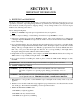
SECTION I IMPORTANT INFORMATION A. RECEIVING and HANDLING The dryer is shipped in a protective stretch wrap cover with protective cardboard corners and top cover (or optional box) as a means of preventing damage in transit. Upon delivery, the dryer and/or packaging, and wooden skid should be visually inspected for shipping damage. If any damage whatsoever is noticed, inspect further before delivering carrier leaves. Dryers damaged in shipment: 1.
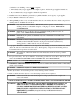
d. Clear the room, building, or area of ALL occupants. e. Immediately call your gas supplier from a neighbor's phone. Follow the gas supplier's instructions. f. If you cannot reach your gas supplier, call the fire department. 4. Installation and service must be performed by a qualified installer, service agency, or gas supplier. 5. Dryers must be exhausted to the outdoors. 6.
SECTION II SPECIFICATIONS/COMPONENT IDENTIFICATION A. SPECIFICATIONS Steam Gas BASKET (TUMBLER) DIAMETER BASKET (TUMBLER) DEPTH BASKET (TUMBLER) MOTOR BLOWER MOTOR DOOR O PENING (DIAMETER) BASKET (TUMBLER) VOLUME DRYERS PER 20'/40'' CONTAINER DRYERS PER 45'/48' TRUCK VOLTAGE AVAILABLE APPROX. WEIGHT (UNCRATED) APPROX. WEIGHT (CRATED) HEAT INPUT AIRFLOW Inlet Pipe Size VOLTAGE AVAILABLE APPROX. WEIGHT (UNCRATED) APPROX. WEIGHT (CRATED) AIRFLOW AIR CONNECTION STEAM COMSUMPTION 375 lbs/hr 170.
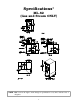
Specifications* ML-82 (Gas and Steam ONLY) NOTE: ADC reserves the right to make changes in specifications at any time, without notice or obligation.
B. COMPONENT IDENTIFICATION 1. Dryer Front View Illus. No.
2. Dryer Rear View Illus. No. 1 2 3* 4 5 6 7 8 Description Heating Unit 1/8" Compressed Air Supply Inlet (behind Electric Service Relay Box for Steam Models ONLY) Electric Service Relay Box Tumbler Bearing Mount Assembly Idler Bearing Mount Assembly Basket (Drive) Motor Assembly (for Reversing Models ONLY) Blower Motor Assembly Dryer Exhaust * Electric service connections for Gas Models and Steam Models are made in this box.
SECTION III INSTALLATION PROCEDURES Installation should be performed by competent technicians in accordance with local and state codes. In the absence of these codes, the installation must conform to applicable American National Standards: National Fuel Gas Code ANSI.Z223.1-LATEST EDITION and/or National Electric Code ANSI/NFPA NO. 70-LATEST EDITION. A. LOCATION REQUIREMENTS Before installing the dryer, be sure the location conforms to local codes and ordinances.
B. UNPACKING/SETTING UP Remove protective shipping material (i.e., plastic wrap, and optional shipping box) from dryer. IMPORTANT: Dryer must be transported and handled in an upright position at ALL times. The dryer can be moved to its final location with or without the skid attached. To un-skid the dryer, locate and remove the four (4) bolts securing the base of the dryer to the wooden skid.
C. DRYER ENCLOSURE REQUIREMENTS Bulkheads and partitions should be made of noncombustible materials and must be located a minimum of twelve (12) inches (18 inches or more is recommended for ease of installation, maintenance , and service) above the dryer outer top, except along the front of the dryer which may be partially closed in if desired. The clearance between the bulkhead header and the dryer must be a minimum of four (4) inches and must not extend more than four (4) inches to the rear of the front.
IMPORTANT: Even though a minimum of only 12 inches is required, 18 inches or more is suggested. The additional clearance is advantageous for ease of installation and service. IMPORTANT: When fire sprinkler systems are located above the dryers, a minimum of 18 inches above the dryer console (module) is required. Dryers may be positioned side wall to side wall however, a 1/16" minimum allowance is required between dryers (or wall) for ease of installation and maintenance.
To compensate for the use of registers or louvers used over the openings, this makeup air must be increased by approximately thirty-three percent (33%). Makeup air openings should not be located in an area directly near where exhaust vents exit the building. It is not necessary to have a separate makeup air opening for each dryer. Common makeup air openings are acceptable. However, they must be set up in such a manner that the makeup air is distributed equally to ALL the dryers.
ALL duct work should be smooth inside with no projections from sheet metal screws or other obstructions which will collect lint. When adding ducts, the duct to be added should overlap the duct to which it is to be connected. ALL duct work joints must be taped to prevent moisture and lint from escaping into the building. Inspection doors should be installed at strategic points in the exhaust duct work for periodic inspection and clean-out of lint from the duct work.
2. Single Dryer Venting Where possible, it is suggested to provide a separate exhaust duct for each dryer. The exhaust duct should be laid out in such a way that the duct work travels as directly as possible to the outdoors with as few turns as possible. It is suggested that the use of 90° turns in the ducting be avoided; use 30° and/or 45° angles instead. The shape of the exhaust duct work is not critical so long as the minimum cross section area is provided.
IMPORTANT: For extended duct work runs, the cross section area of the duct work can only be increased to an extent. When the duct work approaches the maximum limits noted in this manual, a professional heating venting air conditioning (HVAC) firm should be consulted for proper venting information. ALL duct work should be smooth inside with no projections from sheet metal screws or other obstructions which will collect lint.
IMPORTANT: Exhaust back pressure measured by a manometer at each dryer exhaust duct area should not exceed .3" of water column. The duct work should be smooth inside with projections from sheet metal screws or other obstructions which will collect lint. When adding ducts, the duct to be added should overlap the duct to which it is to be connected . ALL duct work joints must be taped to prevent moisture and lint from escaping into the building.
18
F. ELECTRICAL INFORMATION 1. Electrical Requirements It is your responsibility to have ALL electrical connections made by a properly licensed and competent electrician to assure that the electrical installation is adequate and conforms with local and state regulations or codes. In the absence of such codes, ALL electrical connections, material, and workmanship must conform to the applicable requirements of the National Electrical Code ANSI/NFPA NO.70-LATEST EDITION..
2. Electrical Service Specifications MLG-82 (Gas) MLS-82 (Steam) ELECTRIC SERVICE SPECIFICATIONS (PER DRYER) IMPORTANT: 208 VAC and 240 VAC ARE NOT THE SAME. When ordering, specify exact voltage. NOTE: A. B. SERVICE VOLTAGE 208 240 380 416 460/480 Fuse ratings are dual-element, time-delay, current limiting, class RK1 or RK5 ONLY. Circuit breakers are thermal magnetic (industrial) type ONLY. For others, calculate/verify correct breaker size according to appliance amp draw rating and type of breaker used.
3. Electrical Connections NOTE: A wire diagram is located in the front electrical control box for connection data. a. GAS MODELS and STEAM MODELS ONLY NOTE: A CIRCUIT SERVING EACH DRYER MUST BE PROVIDED. 1) Single-phase (1ø) Wiring Connections (Hookup) The electrical connections on ALL single-phase (1ø) gas models and steam model dryers are made into the rear service box located at the upper left area of the dryer.
G. GAS INFORMATION It is your responsibility to have all plumbing connections made by a qualified professional to assure the gas plumbing installation is adequate and conforms with local and state regulations or codes. In the absence of such codes, all plumbing connections, material, and workmanship must conform to the applicable requirements of the National Fuel Gas Code ANSI Z223.1-LATEST EDITION.
a. Gas Connections: Inlet connection Inlet supply size 1 inch N.P.T. 1 inch N.P.T. (minimum) Btu/hr input (per dryer) 270,000 1.Natural Gas Regulation is controlled by the dryer's gas valve's internal regulator. Incoming supply pressure must be consistent between a minimum of 6.0 inches and a maximum of 12 inches water column pressure. 2. Liquid Propane (L.P.) Gas Dryers made for use with L.P.
3. PIPING AND CONNECTIONS ALL components and materials must conform to national fuel gas code specifications. It is important that gas pressure regulators meet applicable pressure requirements and that gas meters be rated for the total amount of all the appliance btu's being supplied. The dryer is provided with a 1 inch N.P.T. inlet pipe connection extending out the back area of the burner box. The minimum pipe size connection (supply line) to the dryer is one inch N.P.T.
25
H. STEAM INFORMATION It is your responsibility to have all steam plumbing connections made by a qualified professional to assure that the installation is adequate and conforms with local and state regulations or codes. IMPORTANT: Failure to comply with the requirements stipulated in this manual can result in component failure which will VOID THE WARRANTY. NOTE: The ML-82 is manufactured with a pneumatic (piston) damper system which requires an external supply of clean, dry, regulated air (80 psi ±10 psi).
d. Shut-off valves for each dryer should be installed in the supply, return, and drip trap return lines. This will allow the dryer to be isolated from the supply and return mains if the dryer needs maintenance work. e. Install an inverted bucket steam trap and check valve for each unit at least 12 inches below steam coil as close to the coil as possible. 1. A trap with a capacity of 1,000 pounds of condensate per hour at 126 psi is needed for each unit. f.
3. STEAM DAMPER AIR SYSTEM CONNECTIONS The MLS-82 is manufactured with a pneumatic (piston) damper system which requires an external supply of compressed air. The air connection is made to the steam damper solenoid valve which is located at the rear inner top area of the dryer just above the electric service relay box. a. Air Requirements Compressed Air Supply Air Pressure Normal 80 psi Minimum Supply 70 psi Maximum Supply 90 psi b. Air Connection Air connection to system 1/8 inch N.P.T. c.
5. STEAM DAMPER AIR PISTON (FLOW CONTROL) OPERATION ADJUSTMENT Although the damper operation was tested and adjusted prior to shipping at 80 psi, steam damper operation must be checked before the dryer is put into operation. Refer to pages 31 and 32 for instructions to check steam damper operation. If damper air adjustment is necessary, locate flow control valve and make necessary adjustments as noted below.
I. PREPARATION FOR OPERATION/START-UP The following items should be checked before attempting to operate the dryer: 1. Read ALL "CAUTION," "WARNING," and "DIRECTION" labels attached to the dryer. 2. Check incoming supply voltage to be sure that it is the same as indicated on the dryer data label affixed to the back side of the top front control/service door. In the case of 208 VAC or 230/240 VAC, THE SUPPLY VOLTAGE MUST MATCH THE ELECTRIC SERVICE EXACTLY. 3.
J. PREOPERATIONAL TESTS ALL dryers are thoroughly tested and inspected before leaving the factory. However, a preoperational test should be performed before the dryer is publicly used. It is possible that adjustments have changed in transit or due to marginal location (installation) conditions. 1. Turn on electric power to the dryer. a. Open ALL shut-off valves (Gas Models Only) 2. Refer to the Operating Instructions for starting your particular model dryer. 3. Gas Dryers a.
Electrically Heated Dryers a. Check to insure that electric oven/contactor assembly is activating. 4. Make a complete operational check of ALL safety related circuits: a. Door Switch(es) b. Hi-Limit thermostats c. Sail switch (for Gas & Electric Models Only) NOTE: To check for proper sail switch operation (for Gas & Electric Models Only), open the main door and while holding main door switch plunger in, start dryer. Dryer should start but heat circuit should not be activated (on).
8. REVERSING MODELS ONLY - basket (tumbler) dryer should never be operated with less than a 30 lb. load (dry weight). The size of the load will affect the coast-down and dwell (stop) times. The basket (tumbler) must come to a complete stop before starting in opposite direction. a. Microprocessor Models 1.
L. SHUT DOWN INSTRUCTIONS If the dryer is to be shut down (taken out of service) for a period of time, the following must be performed: 1. Discontinue power to the dryer either at the external disconnect switch or the circuit breaker. 2. Discontinue the heat supply: a. GAS MODELS ... discontinue the gas supply. 1) SHUT OFF external gas supply shut-off valve. 2) SHUT OFF internal gas supply shut-off valve located in the gas valve burner area. b. STEAM MODELS ... discontinue the steam supply.
SECTION IV SERVICE/PARTS INFORMATION A. SERVICE 1. Service must be performed by a qualified trained technician, service agency, or gas supplier. If service is required, contact the distributor from whom the ADC equipment was purchased. If the distributor cannot be contacted or is unknown, contact the ADC Service Department for a distributor in your area.
SECTION V WARRANTY INFORMATION A. RETURNING WARRANTY CARD(S) 1. Before any dryer leaves the ADC factory test area, a warranty card (ADC Part No. 112254) is placed on the back side of the main door glass. These warranty cards are intended to serve the customer where we record the individual installation date and warranty information to better serve you should you file a warranty claim. a. If a warranty card (ADC Part No.
2. Each part must be tagged with the following information: a. Model and serial numbers of the dryer from which part was removed. b. Nature of failure (be specific). c. Date of dryer installation. d. Date of part failure. e. Specify whether the part(s) being returned is for a replacement, a credit, or a refund. NOTE: If a part is marked for a credit or a refund, the invoice number covering the purchase of the replacement part must be provided. NOTE: Warranty tags (ADC Part No.
SECTION VI ROUTINE MAINTENANCE A. CLEANING A program or schedule should be established for periodic inspection, cleaning, and removal of lint from various areas of the dryer, as well as throughout the duct work system. The frequency of cleaning can best be determined from experience at each location. Maximum operating efficiency is dependent upon proper air circulation. The accumulation of lint can restrict this air flow.
STEAM DRYERS Clean the steam coil fins. Suggest using compressed air and a vacuum cleaner with brush attachment. NOTE: When cleaning steam coil fins, be careful not to bend the fins. If the fins are bent, straighten by using a fin comb, which is available from any local air conditioning supply house. 90 DAYS 1. Remove lint from around basket (tumbler), drive motors, and surrounding areas. 2. Remove lint from gas valve burner area with a dusting brush or vacuum cleaner attachment. 3.
C. LUBRICATION 1. Impellor (fan) shaft bearing must be lubricated every three (3) months. 2. The motor bearing, idler bearings, and tumbler bearings are permanently lubricated. NO LUBRICATION IS NECESSARY. D. LINT DRAWER REMOVAL To remove the lint drawer from the dryer pull drawer out approximately half way. Rotate and move lint drawer stop hinge (refer to the illustration below) downward and pull drawer out. IMPORTANT: After reinstalling the lint drawer back to the upward stop position.
SECTION VII PROCEDURE FOR FUNCTIONAL CHECK OF REPLACEMENT COMPONENTS 1. Microprocessor (computer) Board a. Upon completing installation of the replacement microprocessor (computer) board, reestablish power to the dryer. b. Start the drying cycle by pressing any of the preset cycles in letters A-F. c. Verify that the motor(s) and the heat indicator dots, in the microprocessor (computer) L.E.D. display are on. (Refer to the illustration below.) 1.Basket (tumbler) in Forward Mode (clockwise) 2.
Verify that the motor(s) heat, and door indicator lights on the back side of the microprocessor (computer) board are lit. (refer to the illustration below): 1. 2. 3. 4. 5. 6. 7. 8. 9. 10. 11. 12. "FAN" (Blower) L.E.D. indicator "FOR" (Forward) output L.E.D. indicator (for optional Reversing Models Only) "Rev" (Reverse) output L.E.D. indicator (for optional Reversing Models Only) "HT 1" (Heat) output L.E.D. indicator "Fuse" (Main Fuse) input L.E.D. indicator "Lint" (Lint Door) input L.E.D.
d. Open main door. The dryer must stop and ALL output indicator lights on the back side of the microprocessor (computer) board must go out. (Refer to the illustration on previous page [page 42].) e. Try to restart the dryer with the main door open. f. The microprocessor (computer) board's L.E.D. display must read "DOOR." g. Close the main door and restart the dryer. h. Functional check of microprocessor (computer) board is complete . 2. Hot Surface Ignition (HSI) System a.
SECTION VIII REVERSING TIMER SPIN/DWELL ADJUSTMENTS Dual timer models with "reversing option" have an electric reversing timer in the electric service box which is located in the upper rear area of the dryer. Both the dwell (stop) time and basket (tumbler) spin time are adjustable by mode selection switches located on the electronic timer (as noted in the illustration below).
SECTION IX TECHNICAL INFORMATION A. DATA LABEL Contact American Dryer Corporation When contacting American Dryer Corporation certain information is required to insure proper service / parts information from American Dryer. This information is on the data label located on the inside of the control door. When contacting American Dryer please have the model number and serial number available.
THE DATA LABEL 1. MODEL DRYER The model number is an ADC number which describes the size of the dryer and the type of heat (gas, electric, or steam). 2. SERIAL NUMBER The serial number allows ADC to gather information on your particular dryer. 3. MANUFACTURING CODE NUMBER The manufacturing code number is a number issued by ADC which describes ALL possible options on your particular model. 4.
ADC 113051 1- 11/03/98-15 4* 03/25/99-50 7* 02/24/00-20 2- 12/08/98-5 5- 05/25/99-100 8- 02/25/00-150 3- 02/01/99-5 6* 09/21/99-100