Liebert® DataMate™–1.5 to 3 Tons (5 to 10.
TABLE OF CONTENTS 1.0 INTRODUCTION . . . . . . . . . . . . . . . . . . . . . . . . . . . . . . . . . . . . . . . . . . . . . . . . . . . . . . . . . .1 1.1 Designed to Match Computer and Electronic Equipment Needs—From Installation to Operation . . . . . . . . . . . . . . . . . . . . . . . . . . . . . . . . . . . . . . . . . . . . . . . . . . . . . . . . . . . . . . . . 1 2.0 STANDARD FEATURES—1.5- TO 3-TON SYSTEMS . . . . . . . . . . . . . . . . . . . . . . . . . . . . . . . .2 2.
Figure 7 Figure 8 Figure 9 Figure 10 Figure 11 Figure 12 Figure 13 Figure 14 Figure 15 Figure 16 Figure 17 Figure 18 Figure 19 Figure 20 Figure 21 Figure 22 General arrangement, water/glycol, split systems . . . . . . . . . . . . . . . . . . . . . . . . . . . . . . . . . . . . . General arrangement, water/glycol systems, close-coupled condensing unit . . . . . . . . . . . . . . . . Dimensions, evaporator unit . . . . . . . . . . . . . . . . . . . . . . . . . . . . . . . . . . . . . . . . . . . . . . . . .
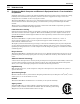
Introduction 1.0 INTRODUCTION 1.1 Designed to Match Computer and Electronic Equipment Needs—From Installation to Operation Installed on the floor or on the wall, Liebert DataMate Precision Cooling systems control the cooling, humidity and air distribution required by sensitive electronic equipment. A range of sizes and configurations is available to meet varying sites’ needs. The Liebert DataMate is also easy to use.
Standard Features—1.5- to 3-Ton Systems 2.0 STANDARD FEATURES—1.5- TO 3-TON SYSTEMS 2.1 Evaporator Section—Split-Systems The Liebert DataMate is available as a split system air, water/glycol-cooled unit or self-contained chilled water unit. Split-System Evaporator Section includes the evaporator coil, 2-speed centrifugal blower assembly, filter-drier, galvanized steel drain pan, R-407C refrigerant charge, cleanable filters and microprocessor control with wall-mounted display panel.
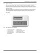
Standard Features—1.5- to 3-Ton Systems 2.5 System Controls System controls include a microprocessor control board mounted in the evaporator/chilled water unit and a wall-mounted interface with a two-line, 16-character liquid crystal display. An eight-key, membrane keypad for setpoint/program control, unit On/Off, fan speed and alarm silence is below the LCD screen.
Optional Factory-Installed Features—Evaporator/Chilled Water and Condensing Units 3.0 OPTIONAL FACTORY-INSTALLED FEATURES—EVAPORATOR/CHILLED WATER AND CONDENSING UNITS 3.1 Electric Reheat Electric low watt tubular reheat element with non-corrosive metal sheath provides one stage of non-ionizing reheat to maintain room dry bulb temperature. 3.2 Humidifier/Electric Reheat Package The humidifier and electric reheat are available as a package for complete humidity control.
Ship-Loose Accessories—Field-Installed 4.0 SHIP-LOOSE ACCESSORIES—FIELD-INSTALLED The Condensate Pump is field-mounted internal to the unit and wired to the unit power block or is field-mounted external to the unit with power from unit or external power supply. Pump is complete with integral float switch, discharge check valve, pump, motor assembly and reservoir. A secondary float can be field-wired to shut down the unit upon high condensate level.
Ship-Loose Accessories—Field-Installed 4.1 Remote Monitoring, Autochangeover and Leak Detection Equipment The Liebert RCM4™ is a four-point, normally open, dry contact monitoring panel. One Form-C, dry contact common alarm relay output (rated at 24 VAC, 3 Amp) is provided. Four red LEDs illuminate on the respective alarm and the alarm buzzer is silenced by a front panel switch. The RCM4 requires a 24VAC or 24VDC power source. Power supply is not included.
Flexible Configurations 5.0 FLEXIBLE CONFIGURATIONS Figure 2 Flexible configurations—All systems Air-Cooled Systems L ie be rt ¨ ¨ Liebert OUTDOOR, AIR-COOLED CONDENSING UNIT Suitable for installation on a roof or at ground level. INDOOR AIR-COOLED CONDENSING UNIT For applications where roof or ground level locations are impractical. Water/Glycol-Cooled Systems L ie be ¨ Liebert WATER/GLYCOL-COOLED CLOSE-COUPLED A single power and water supply connection puts the unit in operation.
Air-Cooled Systems—Capacities and Dimensions 6.0 Table 1 AIR-COOLED SYSTEMS—CAPACITIES AND DIMENSIONS 60Hz capacities & typical specifications, air-cooled applications Evaporator Model DME020E PFH - Outdoor DME027E DME037E Condensing Unit Type DX Evaporator- Net Capacity Data - kW (Btuh) @ High Speed CFM 80°F DB, 62.8°F WB Total 5.50 (18,800) 7.20 (24,500) (26.7°C DB, 17.1°C Sensible 5.50 (18,800) 7.20 (24,500) WB) 38 %RH 75°F DB, 61°F WB Total 5.10 (17,400) 6.70 (22,800) (23.9°C DB, 16.
Air-Cooled Systems—Capacities and Dimensions Table 2 50Hz capacities & typical specifications, air-cooled applications DME037E Evaporator Model PFH - Outdoor MCD - Indoor Total 10.60 (36,200) 9.55 (32,600) Sensible 9.40 (32,100) 8.90 (30,400) Condensing Unit Type DX Evaporator- Net Capacity Data - kW (Btuh) @ High Speed CFM 80°F DB, 62.8°F WB (26.7°C DB, 17.1°C WB) 38 %RH 75°F DB, 61°F WB (23.9°C DB, 16.1°C WB) 45 %RH 72°F DB, 60°F WB (22.2°C DB, 15.5°C WB) 50 %RH Total 10.25 (34,900) 9.
Air-Cooled Systems—Capacities and Dimensions Figure 3 General arrangement, air-cooled split systems Condenser Coil High Pressure Switch Scroll Compressor Hot Gas Bypass Solenoid Valve Liquid Injection Valve Bulb Suction Line Male Quick Connect Coupling Suction Line Female Quick Connect Coupling External Equalizer * Sensing Bulb Liquid Injection Valve s ypas as B Hot G ol Valve r Cont Liquid Line Solenoid Valve Service Access Ports Filter Drier 3 - Way Head Pressure Relief Valve 3/8" SAE 45° Ma
Air-Cooled Systems—Capacities and Dimensions Figure 4 Dimensions, evaporator unit Grilles are reversible to allow air direction changes as shown by the arrows Air Outlet A Removable Access Panel Shaded area indicates a recommended clearance of 34" (864mm) in front of the unit.
Air-Cooled Systems—Capacities and Dimensions Figure 5 Cabinet and floor planning dimensions—Outdoor air-cooled condensing units Fan Rotation CCW (left side) Removable (right) panel for access to refrigeration component A Right Air Discharge Left Air Intake Shaded area indicates a minimum clearance of 18" (457mm) for proper air flow. B Shaded area indicates a recommended clearance of 24" (610mm) for component access and removal.
Air-Cooled Systems—Capacities and Dimensions Figure 6 Dimensions, indoor air-cooled condensing units Customer Supplied Threaded Rods for Module Support from Ceiling (typ.
Water/Glycol Systems—Capacities and Dimensions 7.0 Table 7 WATER/GLYCOL SYSTEMS—CAPACITIES AND DIMENSIONS 60Hz capacities & typical specifications, water-cooled and glycol-cooled applications Evaporator Model DME020E WaterGlycolCooled Cooled @ High Speed CFM 5.90 (20,100) 5.15 (17,600) 5.80 (19,800) 5.15 (17,600) 5.50 (18,800) 4.80 (16,300) 5.15 (17,600) 4.75 (16,200) 5.35 (18,100) 4.60 (15,700) 4.75 (16,200) 4.
Water/Glycol Systems—Capacities and Dimensions Table 8 50Hz capacities & typical specifications, water-cooled and glycol-cooled applications DME037E Evaporator Model Water-Cooled Glycol-Cooled Total 11.3 (38,700) 9.30 (31,800) Sensible 9.55 (32,600) 8.60 (29,300) Total 11.0 (37,400) 8.95 (30,500) Sensible 8.55 (29,200) 7.60 (26,000) Total 10.7 (36,600) 8.75 (29,900) Sensible 7.95 (27,200) 7.
Water/Glycol Systems—Capacities and Dimensions Figure 7 General arrangement, water/glycol, split systems High Pressure Scroll Compressor Switch Liquid Injection Valve Bulb Tube-in-Tube Condenser Hot Gas Bypass Solenoid Valve Suction Line Male Quick Connect Coupling Tube-in-Tube Condenser Suction Line Female Quick Hot Gas Bypass Water/Glycol * Connect Coupling Control Return Line Sensing Valve External Water/Glycol Bulb Liquid Fluid Return Equalizer Supply Line Injection From Unit Valve Shutoff ** Val
Water/Glycol Systems—Capacities and Dimensions Figure 9 Dimensions, evaporator unit Grilles are reversible to allow air direction changes as shown by the arrows Air Outlet A Removable Access Panel Shaded area indicates a recommended clearance of 34" (864mm) in front of the unit.
Water/Glycol Systems—Capacities and Dimensions Figure 10 Dimensions and piping, close-coupled water/glycol condensing unit el an ) P ss able ce Ac mov e (R 14" (356mm) Floor Liebert DataMate Evaporator 32" (813mm) Access Panel (Removable) Condensing Unit Access Panel (Removable) 12" (305mm) Unit Dimensions Shaded area indicates a recommended clearance of 34" (864mm) in front of the unit and 12" (305mm) on the left side for component access and removal.
Water/Glycol Systems—Capacities and Dimensions Table 11 Net weight, water/glycol condensing units Model Tons Weight DMC022WG 1-1/2 170lb (77kg) DMC029WG 2 170lb (77kg) DMC040WG 3 170lb (77kg) Source: DPN000269, Rev. 0 Table 12 Unit refrigerant connection sizes Unit Refrigerant Connections Internal Pipe Size/ Coupling No. Water/Glycol Piping Connection Sizes O.D.
Water/Glycol Systems—Capacities and Dimensions Figure 11 Cabinet dimensions and piping data, water/glycol indoor remote condensing modules 14" (356mm) Overall Cabinet Dimension 8-7/8" (225mm) 50-1/4" (1276mm) Overall Dimension 3-7/8" (98mm) 48-1/4" (1225mm) Threaded Rod Centers 181mm) 46-1/2" (1 ension Cabinet Dim 8-7/16" (214mm) 12" (305mm) Threaded Rod Centers 20-3/4" (527mm) 22-1/2" (572mm) Cabinet Dimension Customer Supplied Threaded Rods for Module Support from Ceiling (typ.
Chilled Water Systems 8.0 CHILLED WATER SYSTEMS Table 14 Chilled water data, 50/60Hz DME044C 208/230-1-60 CW Model, 60 Hz 200/220-1-50 Net Capacity Data - kW (Btuh) based on 45°F (7.2°C) EWT & 10°F (5.6°C) temperature rise 80°F DB, 62.8°F WB (26.7°C DB, 17.1°C WB) 38 %RH Total 10.5 (35,800) 9.05 (30,900) Sensible 9.65 (33,000) 8.25 (28,200) 7.3 (27.7) 6.3 (23.9) Flow Rate, GPM (l/m) Pressure Drop, ft. water (kPa) 75°F DB, 61°F WB (23.9°C DB, 16.1°C WB) 45 %RH 12.5 (37.4) 9.7 (29.
Chilled Water Systems Table 15 Chilled water capacity correction factors based on 10°F (5.6°C) water rise 72°F (22.2°C) 50% 75°F (23.9°C) 45%RH EWT TCC SCC TCC SCC 42°F (5.6°C) 1.27 1.14 1.23 1.11 43°F (6.1°C) 1.17 1.09 1.15 1.07 44°F (6.7°C) 1.08 1.04 1.07 1.04 45°F (7.2°C) 1.00 1.00 1.00 1.00 46°F (7.8°C) 0.93 0.96 0.94 0.96 47°F (8.3°C) 0.86 0.92 0.88 0.93 48°F (8.9°C) 0.79 0.88 0.82 0.89 49°F (9.4°C) 0.74 0.83 0.77 0.
Chilled Water Systems Figure 13 Dimensions—Chilled water unit Grilles are reversible to allow air direction changes as shown by the arrows Air Outlet A Removable Access Panel Shaded area indicates a recommended clearance of 34" (864mm) in front of the unit. Air Inlet 32" (813mm) Standard Refrigeration and Chilled Water Piping Opening 5/8" (16mm) FLOOR CUTOUT DIMENSIONS for Raised-Floor Piping 3-1/2" (89mm) A Cabinet Outline 1" (25mm) Table 16 Model DME044C 10-7/8" (276mm) DPN000262 Rev.
Electrical Data—All Units 9.0 ELECTRICAL DATA—ALL UNITS Table 17 Electrical data, split system evaporator or chilled water unit, 60/50Hz 208/230V-1ph-60Hz Base Evaporator/ Chilled Water DME020E DME027E 200/220V-1-50 DME037E DME044C DME020E DME027E DME037E DME044C Cooling Only FLA 1.4 1.5 2.2 1.4 1.5 2.2 WSA 1.8 1.9 2.8 — — — OPD 15 15 15 — — — With Reheat FLA 11.8 22.3 23.0 11.8 22.3 23.0 WSA 14.8 27.9 28.
Electrical Data—All Units Table 19 60Hz electrical data, outdoor air-cooled condensing unit 1.5 Nom. Capacity, Tons 2 3 3 3 3 PFH037A-PL7 PFH037A-YL7 PFH037A-AL7 PFH037A-BL7 Standard 95°F (35°C) Propeller Fan Condensing Unit Model PFH020A-PL7 PFH027A-PL7 Volt-Ph-Hz 208/230-1-60 208/230-1-60 208/230-1-60 208/230-3-60 460-3-60 575-3-60 FLA 12.1 13.4 18.5 13.4 7.1 5.8 WSA 14.8 16.4 22.8 16.4 8.7 7.
Electrical Data—All Units Table 21 Electrical data, indoor air & water/glycol remote condensing units, 50 & 60Hz 60 Hz Model 208/230-1ph-60Hz 277-1ph-60Hz 50 Hz 208/230-3ph-60Hz 460-3ph-60Hz 220-1ph-50Hz 380/415-3ph-50Hz MC*24A MC*24A — — — — FLA 14.3 12.7 — — — — WSA 17.3 15.3 — — — — OPD 25 25 — — — — MC*36A MC*36A MC*36A MC*36A MC*35A MC*35A FLA 20.8 16.6 15.7 7.8 20.1 7.8 WSA 25.1 20.2 18.7 9.
Refrigerant Piping 10.0 REFRIGERANT PIPING Table 22 Refrigerant charge 60 Hz 50 Hz Charge R-407C, oz (kg) DME020E — 4 (0.11) DME027E — 5 (0.14) DME037E DME037E 6.5 (0.18) MC*24AL_H7 — 134 (3.80) MC*36AL_H7 MC*35AL_H7 213 (6.04) MC*26W__H7 — 41 (1.16) MC*38W__H7 MC*37W__H7 54 (1.54) DMC022WG — 47 (1.33) DMC029WG — 59 (1.67) DMC040WG — 61 (1.72) PFH020A-_L7 — 134 (3.80) PFH027A-_L7 — 134 (3.80) PFH027A-_H7 — 213 (6.04) PFHZ27A-_L7 — 213 (6.
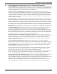
Refrigerant Piping Table 26 Line charges - refrigerant per 100 ft. (30m) of Type L copper tube R-407C, lb/100 ft. (kg/30m) Line Size, O.D., in. Liquid Line Suction Line 3/8 3.7 (1.7) — 1/2 6.9 (3.1) — 5/8 11.0 (5.0) 0.4 (0.2) 3/4 15.7 (7.1) 0.6 (0.3) 7/8 23.0 (10.4) 1.0 (0.4) 1-1/8 — 1.7 (0.7) 1-3/8 — 2.7 (1.1) Figure 15 Refrigerant piping diagram Pitch down 1/2" (13mm) per 10 ft.
Glycol Loop Piping 11.0 GLYCOL LOOP PIPING Contact Emerson Application Engineering for assistance in choosing correct drycooler models. Refer to Figure 16. Figure 16 Heat rejection loop, multiple drycoolers and multiple indoor units Expansion Tank ______ Gal. (L) HP GPM (l/s) ft. ____(kW) ____ Per Pump @ ____(kPa) FS PUMP PACKAGE Drycooler No.
Model Number Nomenclature—All Systems 12.
Model Number Nomenclature—All Systems Figure 20 Model number nomenclature, close-coupled water/glycol condensing units—60Hz only Liebert DataMate Evaporator Section Nominal Capacity (kBtuh) WG = Water/Glycol P = 208/230/1/60 DMC 040 WG P 07 07 = R-407C Refrigerant Figure 21 Model number nomenclature—Indoor remote water/glycol-cooled condensing units Nominal Capacity 26 = 2-ton, 60Hz 37 = 3-ton, 50Hz 38 = 3-ton, 60Hz MC = Liebert Mini-Mate2 Style Indoor Condensing Units D = Disconnect Switch 0 = No
Guide Specifications—For Liebert DataMate 1.5- to 3-Ton (5 to 10.5kW) GUIDE SPECIFICATIONS—FOR LIEBERT DATAMATE 1.5- TO 3-TON (5 TO 10.5KW) 1.0 GENERAL 1.1 Summary These specifications describe requirements for an environmental control system. The system shall be designed to maintain temperature and relative humidity conditions within the room. The manufacturer shall design and furnish all equipment to be fully compatible with heat dissipation requirements of the site.
Guide Specifications—For Liebert DataMate 1.5- to 3-Ton (5 to 10.5kW) 2.1.3 Microprocessor Control System The control system shall be microprocessor-based, factory-wired into the system and tested prior to shipment. The wall-mounted control enclosure shall include a 2-line by 16-character LCD providing continuous display of operating status and alarm condition. An 8-key membrane keypad for setpoint/ program control, fan speed selection and unit On/Off shall be located below the display.
Guide Specifications—For Liebert DataMate 1.5- to 3-Ton (5 to 10.5kW) 2.1.4 Alarms 2.1.4.1 Unit Alarms The control system shall monitor unit operation and activate an audible and visual alarm in the event of the following factory preset alarm conditions. • • • • • • • • High Temperature (max 90°F, 32.2°C) Low Temperature (min 35°F, 1.7°C) High Humidity (max 85% RH) Low Humidity (min 15% RH) High Water Alarm - Lockout Unit Operation High Head Pressure Loss of Power Compressor Short Cycle 2.1.4.
Guide Specifications—For Liebert DataMate 1.5- to 3-Ton (5 to 10.5kW) 2.2 Direct Expansion System Components 2.2.1 Direct Expansion Coil The evaporator section shall include an evaporator coil, thermostatic expansion valve and filter-drier. The evaporator coil shall have ___ ft2 (m2) face area, ___ rows deep. It shall be constructed of copper tubes and aluminum fins and have a maximum face velocity of ___ FPM (m/s) at _____ CFM (CMH).
Guide Specifications—For Liebert DataMate 1.5- to 3-Ton (5 to 10.5kW) 2.3 Indoor Remote Water/Glycol-Cooled Condensing Unit The water/glycol condensing unit shall include a scroll compressor, high-pressure switch, coaxial condenser, water-regulating valve, hot gas bypass system and liquid line solenoid valve. A hot gas bypass circuit shall be provided to reduce compressor cycling and improve operation under low-load conditions.
Guide Specifications—For Liebert DataMate 1.5- to 3-Ton (5 to 10.5kW) 2.5.5 Step-Down Transformer A step-down transformer shall be provided for [(Indoor Evaporator) (Close-Coupled Water/Glycol Condensing Unit) (Outdoor Air-Cooled Condensing Unit)] needing 277V input power voltage. The transformer shall be coated with epoxy and contained in an enclosed, non-ventilated electrical box with adaptable mounting brackets, suitable for [(indoor) (outdoor)] mounting. 2.5.
Guide Specifications—For Liebert DataMate 1.5- to 3-Ton (5 to 10.
Technical Support / Service Web Site www.liebert.com Monitoring liebert.monitoring@emerson.com 800-222-5877 Outside North America: +00800 1155 4499 Single-Phase UPS & Server Cabinets liebert.upstech@emerson.