MegaPowerTM 48+ Installation Manual
MegaPowerTM 48+ DO NOT INSTALL THIS PRODUCT IN HAZARDOUS AREAS WHERE HIGHLY COMBUSTIBLE OR EXPLOSIVE PRODUCTS ARE STORED OR USED FCC Compliance This equipment has been tested and found to comply with the limits for a Class A digital device, pursuant to Part 15 of the FCC Rules. These limits are designed to provide reasonable protection against interference when the equipment is operated in a commercial environment.
Installation Manual Contents FCC Compliance ..................................................................................................................................................................... 2 Equipment Modification Caution ........................................................................................................................................... 2 Warranty Disclaimer ..........................................................................................................
MegaPowerTM 48+ Direct Alarm and Relay Connections .................................................................................................................................. 35 Relay Outputs ................................................................................................................................................................... 35 Patch Panel Alarms ...............................................................................................................................
Installation Manual Introduction The MegaPower 48+ matrix switcher/controller is a video routing system with a broad range of functionality. The unit has a compact, wall-mount design enabling it to be installed in the most centralized location with respect to the video inputs. The unit can also be mounted behind other equipment in the rear of a rack at 90° to conserve space for other products or it can be rack mounted at other angles to facilitate easy cable connections.
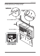
MegaPowerTM 48+ Mechanical Installation 1. Remove the components from Box 1 and arrange them on a surface near the mounting location. 2. Remove and discard the red shipping knobs attached to the patch panel assembly. The knobs are used only for factory packaging and must be removed prior to installation. 3. Using a level, position the installation template where the assembly is to be mounted.
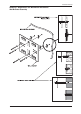
Installation Manual Drawing 1: MegaPower 48+ Mechanical Installation Wall Bracket Assembly 7
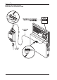
MegaPowerTM 48+ Drawing 2: MegaPower 48+ Mechanical Installation Patch Panel and Wall Bracket Assembly 8
Installation Manual Drawing 3: MegaPower 48+ Mechanical Installation Cable Management Bracket - Tie Wraps and Clips 9
MegaPowerTM 48+ Drawing 4: AC Power Section Patch Panel to Transformer Cable 10
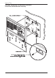
Installation Manual Drawing 5: MegaPower Mechanical Installation Attaching the Main Electronics Unit (MEU) 11
MegaPowerTM 48+ Patch Panel Overview The MegaPower 48+ patch panel contains 8 sections for video switching, communications, power, alarm handling, and auxiliary control. The patch panel also contains a diagnostics section providing system status signals. See Drawing 6, Page 13 for an illustration of the patch panel. A brief description of each patch panel section follows.
Installation Manual Drawing 6: MegaPower 48+ Patch Panel 13
MegaPowerTM 48+ System Programming MegaPower 48+ can be programmed with a system keyboard and monitor using software embedded in the system’s Main Electronics Unit, or with a PC and the Easy 48 software. Instructions for programming are provided in the MegaPower 48+ System Programming and Operating Manual, part number 8000-1804-51. System Integration The MegaPower 48+ system can also be integrated with other American Dynamics security systems and devices.
Installation Manual Drawing 7: Patch Panel to Video Inputs and Video Outputs 15
MegaPowerTM 48+ Cable Networks Cable networks provide the means through which the MegaPower 48+ Main Electronics Unit communicates with receiver/ driver units and domes. Three types of networks can be used with the Manchester, SensorNet, or SEC-RS422 protocols. • Daisy Chain – in a daisy chain configuration, a separate cable connects each device to the next device in the chain (Fig. A). • Backbone – in a backbone configuration, a single, continuous cable connects all domes in the network link (Fig. B).
Installation Manual Drawing 8: Manchester Communications Patch Panel to AD1641 Receiver to AD1240 Pan/Tilt 17
MegaPowerTM 48+ Drawing 9: Manchester Communications Patch Panel to AD2083-02B Code Translator to Integrated Dome 18
Installation Manual Drawing 10: Manchester Communications Patch Panel to AD1691 Code Distributor to Integrated Dome 19
MegaPowerTM 48+ Drawing 11: Manchester Communications Patch Panel to AD2031 Switcher Follower to Audio Circuit 20
Installation Manual Star Connections/AD1691 Code Distributor When the patch panel’s Manchester black, white, and shield terminals are wired to the input terminals of an AD1691 Code Distributor, up to 64 Manchester outputs can be transmitted to receiver/drivers and integrated domes. See Drawing 10, Page 19 for a typical connection utilizing the AD1691.
MegaPowerTM 48+ Drawing 12: Sensornet Communications Patch Panel to 6-Position J-Box to Integrated Dome 22
Installation Manual Drawing 13: RS422 Communications Patch Panel to 10-Position J-Box to Integrated Dome 23
MegaPowerTM 48+ RS232 Communications The RS232 section (PC icon) of the MegaPower 48+ patch panel consists of eight RJ45 receptacles and one DB9 receptacle. • • • Cable required: modular eight conductor cable, cable distance (7 or 14 feet) and plug dependent on application. Accessories: wall-mount keyboard matrix interface (MP-KMI) and wall-mount eight pin terminal box. Box can be single or dual mount dependent on application. Additional Cable: 18 AWG, three-wire, shielded cable.
Installation Manual Drawing 14: RS232 Communications Patch Panel to ADCC1100 Keyboard 25
MegaPowerTM 48+ Drawing 15: RS232 Communications Patch Panel to ADCC0200 and ADCC0300 Keyboards 26
Installation Manual Drawing 16: RS232 Communications Patch Panel to AD2079 and AD2088 Keyboards 27
MegaPowerTM 48+ Drawing 17: RS232 Communications Patch Panel to ADTTE Keyboard 28
Installation Manual Drawing 18: RS232 Communications Patch Panel to AD1981 Port Expander to System Keyboards 29
MegaPowerTM 48+ PC Connection A PC can be connected to the MegaPower 48+ for the purpose of downloading system setup software parameters to the system, or uploading system parameters to the PC. This connection can be via RS232 using a RS232 port on the MegaPower 48+ or via an Ethernet connection using the network connector on the MegaPower 48+.
Installation Manual Drawing 19: RS232 Communications Connections to PC and External Modem 31
MegaPowerTM 48+ Drawing 20: RS232 Communications Patch Panel to AD2096A Alarm Interface Unit to Alarm Contact 32
Installation Manual Drawing 21: RS232 Communications Video Recorder Control via ADCC1100 Keyboard 33
MegaPowerTM 48+ Drawing 22: Ethernet Connections to a PC 34
Installation Manual Direct Alarm and Relay Connections Relay Outputs The MegaPower 48+ patch panel provides a section for direct connection to two normally-open or normally-closed relay outputs for switching of auxiliary devices such as lights, gates, audio alerts, recorders, etc. Patch Panel Alarms The MegaPower 48+ patch panel provides 16 screw terminals and corresponding ground returns for direct connection to normally-open alarm contacts. These connections are referred to as “patch panel” alarms.
MegaPowerTM 48+ Drawing 23: Patch Panel Alarms and Relay Sections 36
Installation Manual Multi-Matrix Configurations MegaPower 48+ units can be connected together in multi-matrix systems. A primary MegaPower 48+ matrix can be connected with up to six secondary matrices, creating a maximum system capacity of 288 video inputs with eight full cross point switched monitor outputs and seven additional monitor outputs on each secondary unit (for viewing of video from that secondary unit only).
MegaPowerTM 48+ Mechanical Installation of Multiple Matrices Each MegaPower 48+ unit in a multi-matrix system must be installed and connected to a power supply as explained in the mechanical installation procedure detailed on page 6. Network Connections in a Multi-Matrix System In a multi-matrix system, matrices can be connected together via Ethernet. All ethernet connections should be made with Cat 5 twisted pair cable with a maximum length of 300 feet.
Installation Manual In a multi-matrix system with more than two matrices, matrices must be connected together via a network switch as shown in the figure below. It is preferable to use a true network switch rather than a hub as a switch only sends data to the relevant port connection while a hub will copy the data to all ports. Straight connections should be made from the network connector on each matrix to the network switch.
MegaPowerTM 48+ Video Connections in a Multi-Matrix System The video connections made in a multi-matrix system will depend on the operation mode that is being used. In all following sections, the maximum number of trunk video connections are shown and by connecting in this manner, the maximum number of full cross point switched monitor outputs can be achieved.
Installation Manual Mode 1: Primary Matrix with 2 Secondary Matrices Consult the figure below in order to connect video inputs and outputs to the system. The 16 monitor outputs from each secondary matrix must be connected to 16 video inputs on the primary matrix. Sixteen full cross point switched monitor outputs are available by connecting monitors to video outputs 1-16 on the primary matrix. PRIMARY MATRIX MONITORS 1-16 (PORT REFS.
MegaPowerTM 48+ Mode 1: Primary Matrix with 3 Secondary Matrices Consult the figure below in order to connect video inputs and outputs to the system. The 16 monitor outputs from each secondary matrix must be connected to 16 video inputs on the primary matrix. Sixteen full cross point switched monitor outputs are available by connecting monitors to video outputs 1-16 on the primary matrix. PRIMARY MATRIX MONITORS 1-16 (PORT REFS.
Installation Manual Mode 2 Configurations Mode 2: Primary Matrix with 1 Secondary Matrix Consult the figure below in order to connect video inputs and outputs to the system. Monitor outputs 4-15 from the secondary matrix must be connected to video inputs 1-12 on the primary matrix. Twelve full cross point switched monitor outputs are available by connecting monitors to video outputs 1-12 on the primary matrix. Monitors can also be connected to monitor outputs 1-3 on the secondary matrix.
MegaPowerTM 48+ secondary matrix must be connected to 8 video inputs on the primary matrix. Eight full cross point switched monitor outputs are available by connecting monitors to video outputs 1-8 on the primary matrix. Monitors can also be connected to monitor outputs 1-7 on each secondary matrix. These monitors can display video inputs from that secondary unit only. On all matrices, video output 16 is reserved for video-loss detection.
Installation Manual Consult the figure below in order to connect video inputs and outputs to the system. Monitor outputs 8-15 from each secondary matrix must be connected to 8 video inputs on the primary matrix. Eight full cross point switched monitor outputs are available by connecting monitors to video outputs 1-8 on the primary matrix. Monitors can also be connected to monitor outputs 1-7 on each secondary matrix. These monitors can display video inputs from that secondary unit only.
MegaPowerTM 48+ Mode 3: Primary Matrix with 5 or 6 Secondary Matrices Consult the figures on page 52 and 53 in order to connect video inputs and outputs to the system. Monitor outputs 8-15 from each secondary matrix must be connected to 8 video inputs on the primary matrix. Eight full cross point switched monitor outputs are available by connecting monitors to video outputs 1-8 on the primary matrix. Monitors can also be connected to monitor outputs 1-7 on each secondary matrix.
Installation Manual RS232 Connections in a Multi-Matrix System Keyboard and Port Expander Connection Keyboards can be connected to any RS232 port in a multi-matrix system. Therefore, in a Mode 3 configuration with six secondary matrices, up to 56 keyboards can be connected (without using port expanders). Any of these keyboards can be used to control any component in the system—keyboards connected to a secondary matrix are NOT limited to control of components connected to the same secondary matrix.
MegaPowerTM 48+ The use of port expanders is also supported in multi-matrix systems, enabling up to four keyboards to be connected to any one RS232 port. This means up to 32 keyboards can be connected to any matrix, and that in a Mode 3 configuration with six secondary matrices, up to 224 keyboards can be connected. A MegaPower 48+ system supports a maximum of 64 active keyboards with a maximum of 20 keyboards performing PTZ operations at any one time.
Installation Manual A compatible modem can only be connected to Port 8 of the RS232 section on the primary matrix. Note, however that only one modem can be added to a multi-matrix system. See page 24 for more details on connecting a modem. Alarm Interface Unit Connection An AD2096A Alarm Interface Unit (AIU) can be connected to any RS232 port in a multi-matrix system. Each AD2096A can be connected with up to 64 alarm contacts, and a maximum of eight units can be connected to the system (i.e.
MegaPowerTM 48+ Peripheral Interface Port Connection MegaPower 48+ embedded software and system setup software provide the user with a system option to enable one Peripheral Interface Port (PIP). This can be any RS2332 port in a multi-matrix system. See page 30 for more details. PC Connection in a Multi-Matrix System In a multi-matrix system, an Ethernet connection can be made between the primary matrix and a PC using a straight CAMERAS 1-48 MONITORS 9-15 (PORT REFS. A1-A48) (PORT REFS.
Installation Manual connection via an Ethernet hub or switch. Alternatively, a PC can be connected directly to a RS232 port on the primary matrix, but it is preferable to use an Ethernet connection when running the Easy 48 configuration software. See page 30 for more details on connecting a PC to a MegaPower 48+.
MegaPowerTM 48+ CAMERAS 1-48 MONITORS 9-15 (PORT REFS. A1-A7) CAMERAS 49-96 (PORT REFS. B1-B7) MONITORS 16-22 (PORT REFS. C1-C48) CAMERAS 97-144 (PORT REFS. C1-C7) MONITORS 23-29 (PORT REFS. E1-E48) CAMERAS 192-240 (PORT REFS. E1-E7) MONITORS 37-43 (PORT REFS. X41-X48) CAMERAS 241-246 (PORT REFS. X1-X8) MONITORS 1-8 CONNECT MONITOR OUTPUTS 815 ON SECONDARY MATRIX C TO VIDEO INPUTS 17-24 ON PRIMARY MATRIX SECONDARY MATRIX C (PORT REFS.
Installation Manual CAMERAS 1-48 MONITORS 9-15 (PORT REFS. A1-A7) CAMERAS 49-96 (PORT REFS. B1-B7) MONITORS 16-22 (PORT REFS. C1-C48) CAMERAS 97-144 (PORT REFS. C1-C7) MONITORS 23-29 CONNECT MONITOR OUTPUTS 8-15 ON SECONDARY MATRIX F TO VIDEO INPUTS 41-48 ON PRIMARY MATRIX (PORT REFS. X1-X8) MONITORS 1-8 CONNECT MONITOR OUTPUTS 8-15 ON SECONDARY MATRIX C TO VIDEO INPUTS 17-24 ON PRIMARY MATRIX SECONDARY MATRIX C (PORT REFS.
MegaPowerTM 48+ Control Addressing Quick Look-Up Table 54
Installation Manual Directive (LVD) 73/23/EEC. The equipment was tested in a typical configuration.
MegaPowerTM 48+ 56
Installation Manual Pearl River, NY, USA 15 September, 2000 Harold D. Johnson, Ph. D. Director of Engineering European Contact: Sensormatic France S.A. 7, rue Alexis de Tocqueville Parc de Haute Technologie, 92183 ANTONY CEDEX MegaPower 48+ Product Specifications System Specification Video Subsystem Video Inputs .............................................. 48 inputs Switched Outputs ...................................... 16 outputs Video Text Overlays ..................................
MegaPowerTM 48+ Video Output Overlay Alpha-Numeric Modes: TV Standards ............................................ NTSC and PAL Character Attributes .................................. Character Intensity, 8 levels Text Background: transparent Character Sets .......................................... English (standard) Display Area Positioning: ..........................
Installation Manual Power-on in-rush current .......................... 10 A (120 VAC); 5 A (230 VAC) Mechanical Specifications Dimensions Depth ........................................................ 8.43cm (3.50") Width ......................................................... 43.69cm (17.25") Height ........................................................ 50.85cm (20") Weight Shipping Weight ........................................ 36.3 kg. (16.5 lb.) max.
MegaPowerTM 48+ interface units Product Codes VR48NC .................................................... 48 x 16 Matrix Switch with no Controller VR48KB .................................................... 48 x 16 Matrix Switch with AD2088 VR48TT ..................................................... 48 x 16 Matrix Switch with ADTTE Compatible Product Listing Non-CE Approved CE Approved Approvals Safety Approvals UL ............................................................. UL1950 CUL or CSA .........
Installation Manual 61
MegaPowerTM 48+ 62
Installation Manual 63
Please visit our website for more information www.americandynamics.