DRD08/DRD14 Series Receiver/Drivers for Intercept® Series Domes Installation/ Operation Manual C466M-E (6/99) Pelco • 3500 Pelco Way, Clovis • CA 93612-5699 USA • www.pelco.
CONTENTS Section Page 1.0 GENERAL .................................................................................................. 5 1.1 IMPORTANT SAFEGUARDS AND WARNINGS ............................... 5 2.0 DESCRIPTION .......................................................................................... 6 2.1 MODELS ............................................................................................ 6 3.0 INSTALLATION .......................................................................
LIST OF ILLUSTRATIONS Figure 1 2 3 4 Page PC Board Locations ........................................................................... 8 CPU Board ......................................................................................... 9 R26/R27 Adjustment Location ........................................................... 9 Receiver/Driver Reset Button Location ............................................. 18 LIST OF TABLES Table A B C Page Switch Settings for SW1 - D-Type Control ..................
(This page intentionally left blank.
1.0 GENERAL 1.1 IMPORTANT SAFEGUARDS AND WARNINGS Prior to installation and use of this product, the following WARNINGS should be observed. 1. Installation and servicing should only be done by Qualified Service Personnel and conform to all Local codes. 2. Unless the unit is specifically marked as a NEMA Type 3, 3R 3S, 4, 4X, 6, or 6P enclosure, it is designed for indoor use only and it must not be installed where exposed to rain and moisture. 3. Only use replacement parts recommended by Pelco. 4.
2.0 DESCRIPTION The DRD08 Series of receiver/drivers is part of the IDS08 Intercept® Series of domes. The IDS08 Series is an integral system that includes a back box (BB08), dome drive (DD08), dome receiver/driver (DRD08), and imager/optics package (IOP08). This manual covers the DRD08 Series of receiver/drivers. For installation and operation instructions for the back box, refer to manual C456M-D; for the dome drive, refer to C416M-C; and for the imager/optics package, refer to C1441M-C.
Pelco Manual C466M-E (6/99) DRD08D22 Receiver/driver for 8" Intercept® dome series. Enhanced receiver with preset positioning, zones, and patterns. For use with variable-speed dome drive. D-type control: RS-422 compatible with Pelco’s MPT9500, CM6700 and CM8500 controllers or with American Dynamics controllers using the AD2083 Translator. DRD14D22 Same as DRD08D22 except for use with 14" Intercept® dome series. DRD08P11 Receiver/driver for 8" Intercept® dome series.
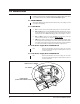
3.0 INSTALLATION Installation of the Dome Receiver/Driver (DRD) into the DD08 or DD14 Dome Drive is accomplished at the factory. This is not a field installable option. 3.1 ADJUSTMENTS Although the DRD has been adjusted and set at the factory, some settings can and may require field adjusting. 3.1.1 CPU Board 1. JP3 is set at the factory in the RS-485 (422) position. Leave it in this position. 2. JP5 and JP6 are both set in the UNTERM (unterminated) position.
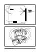
JP2 JP3 JP1 JP5 and JP6 RESET SWITCH JP5 TERMINATED UNTERMINATED JP6 SW1 ON 1 2 3 4 5 6 7 8 MADE IN USA PCB8500110D Figure 2. CPU Board R26/R27 ADJUSTMENT Figure 3.
Table A. Switch Settings for SW1 - D-Type Control NOTES: For Coaxitron® controls, SW1 is not used. For P-type control systems, refer to Table B.
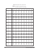
Table A Switch Settings for SW1 - D-Type Control (continued) Receiver Address 49 50 51 52 53 54 55 56 57 58 59 60 61 62 63 64 65 66 67 68 69 70 71 72 73 74 75 76 77 78 79 80 81 82 83 84 85 86 87 88 89 90 91 92 93 94 95 96 97 98 99 100 SW1-1 SW1-2 SW1-3 Switch Setting SW1-4 SW1-5 SW1-6 SW1-7 SW1-8 OFF ON OFF ON OFF ON OFF ON OFF ON OFF ON OFF ON OFF ON OFF ON OFF ON OFF ON OFF ON OFF ON OFF ON OFF ON OFF ON OFF ON OFF ON OFF ON OFF ON OFF ON OFF ON OFF ON OFF ON OFF ON OFF ON ON OFF OFF ON ON OFF O
Table A Switch Settings for SW1 - D-Type Control (continued) Receiver Address 101 102 103 104 105 106 107 108 109 110 111 112 113 114 115 116 117 118 119 120 121 122 123 124 125 126 127 128 129 130 131 132 133 134 135 136 137 138 139 140 141 142 143 144 145 146 147 148 149 150 151 152 SW1-1 SW1-2 SW1-3 Switch Setting SW1-4 SW1-5 SW1-6 SW1-7 SW1-8 OFF ON OFF ON OFF ON OFF ON OFF ON OFF ON OFF ON OFF ON OFF ON OFF ON OFF ON OFF ON OFF ON OFF ON OFF ON OFF ON OFF ON OFF ON OFF ON OFF ON OFF ON OFF ON
Table A Switch Settings for SW1 - D-Type Control (continued) Receiver Address 153 154 155 156 157 158 159 160 161 162 163 164 165 166 167 168 169 170 171 172 173 174 175 176 177 178 179 180 181 182 183 184 185 186 187 188 189 190 191 192 193 194 195 196 197 198 199 200 201 202 203 204 SW1-1 SW1-2 SW1-3 Switch Setting SW1-4 SW1-5 SW1-6 SW1-7 SW1-8 OFF ON OFF ON OFF ON OFF ON OFF ON OFF ON OFF ON OFF ON OFF ON OFF ON OFF ON OFF ON OFF ON OFF ON OFF ON OFF ON OFF ON OFF ON OFF ON OFF ON OFF ON OFF ON
Table A Switch Settings for SW1 - D-Type Control (continued) Receiver Address 205 206 207 208 209 210 211 212 213 214 215 216 217 218 219 220 221 222 223 224 225 226 227 228 229 230 231 232 233 234 235 236 237 238 239 240 241 242 243 244 245 246 247 248 249 250 251 252 253 254 14 SW1-1 SW1-2 SW1-3 Switch Setting SW1-4 SW1-5 SW1-6 SW1-7 SW1-8 OFF ON OFF ON OFF ON OFF ON OFF ON OFF ON OFF ON OFF ON OFF ON OFF ON OFF ON OFF ON OFF ON OFF ON OFF ON OFF ON OFF ON OFF ON OFF ON OFF ON OFF ON OFF ON OFF
Table B. Switch Settings for SW1 - P-Type Control NOTES: For Coaxitron® controls, SW1 is not used. For D-type control systems, refer to Table A.
4.0 OPERATION Upon applying power, the unit starts a configuration routine after 15 seconds. 4.1 SCAN OPERATION Three (3) different scan mode options are offered and can be selected according to operator preference: Auto Scan; (AUX 2), continuous panning, with a 5-second stop on limits. Random Scan; (AUX 3) random operation. Frame Scan; (AUX 4) with 5 seconds of travel followed by 5 seconds of stop. To select a scan mode (at the system controller), select the appropriate AUX button, then select scan. 4.
4.3 PRESET FUNCTIONS NOTE: Preset commands are only in the 32-bit format. NOTE: If the DRD is commanded 1. The DRD***2* units are capable of 32 complete preset scenes. On DRD**A2* models, each preset can have a 20-character label. To set a preset, first enter the label then program the position. 2. Once programmed, the DRD***2* can be commanded to the preset. Resolution of the pan and tilt position is 1/2 degree. 3.
4.6 PATTERNS 1. The DRD***2* units are capable of one 60-second pattern. This pattern can consist of any standard pan/tilt or lens command. Presets, flip and turbo are not allowed in a pattern. Zone scan can be enabled while running a pattern. 2. To program a pattern first move the pan/tilt and adjust the lens to the starting point desired. Engage the Pattern Programming command. The message “PROGRAMMING PATTERN” will be displayed.
5.0 FIRMWARE 5.1 COAXITRON CONTROL COMMAND This section describes the protocol used to send commands to the receivers via Coaxitron. The hardware interface is a 32-bit PWM (pulse width modulated) signal, wherein a one microsecond pulse is considered a zero and a two microsecond pulse is considered a one. There will be a minimum one (1) microsecond off space between pulses. Line 18 will contain Bytes 1 and 2, line 19 will contain Bytes 3 and 4. Commands are divided into two (2) categories.
5.1.2 Extended Commands Extended commands will always have B0 of Byte 2 set to one.
5.2.2 Addressing The address is set on the CPU board PCB8500110. The switch is labeled SW1. Setting the switch in the “ON” position represents a zero. Refer to Table A. NOTE: Do not use addresses 0 or 255. SW1.1 SW1.2 SW1.3 SW1.4 SW1.5 SW1.6 SW1.7 SW1.8 Address Bit 0 Address Bit 1 Address Bit 2 Address Bit 3 Address Bit 4 Address Bit 5 Address Bit 6 Address Bit 7 5.2.3 PTZ (Pan/Tilt and Lens) Commands All PTZ (pan/tilt and lens) commands will always have B0 of word 4 set to zero.
5.2.4 Extended Commands Extended commands will always have B0 of Word 4 set to one.
5.3.2 Addressing The address is set on the CPU board PCB8500110. The switch is labeled SW1. Setting the switch in the “ON” position represents a zero. The first five positions set the receiver address (1 through 5) from a range of 0 to 31. The last three (6 through 8) set the baud rate. Refer to Table B. SW1.1 — Address Bit 0 SW1.2 — Address Bit 1 SW1.3 — Address Bit 2 SW1.4 — Address Bit 3 SW1.5 — Address Bit 4 SW1.6 — 9600 Baud SW1.7 — 4800 Baud SW1.8 — 2400 Baud 5.3.
5.3.4.2 Extended Commands Extended commands will always have B0 of Word 4 set to 1. The numbers below are in hexadecimal format. NOTE: The extended commands above are available at the receiver; make sure commands can be initiated by the controlling system.
6.0 CIRCUIT BOARD PARTS LIST Table C.
7.0 SPECIFICATIONS Input Voltage: Maximum Input Power AC Motor Dome Drive: DC Stepper Motor Dome Drive: 24 VAC, 60 Hz, ±10% at the drive Pan — 7.5 vA Tilt — 7.5 vA Idle — 2.5 vA Pan — 32 vA Tilt — 32 vA Pan/Tilt — 48 vA Idle — 15 vA Camera Output Voltage: 24 VAC Lens Output Voltage: 9 to 12 VDC (Bi-polar) Video Input Level: 0.5 to 1.
7.1 REGULATORY NOTICES NOTE: This equipment has been tested and found to comply with the limits of a Class A digital device, pursuant to part 15 of the FCC rules. These limits are designed to provide reasonable protection against harmful interference when the equipment is operated in a commercial environment. This equipment generates, uses, and can radiate radio frequency energy and, if not installed and used in accordance with the instruction manual, may cause harmful interference to radio communications.
8.0 WARRANTY AND RETURN INFORMATION WARRANTY Pelco will repair or replace, without charge, any merchandise proved defective in material or workmanship for a period of one year after the date of shipment. Exceptions to this warranty are as noted below: • Five years on FT/FR8000 Series fiber optic products. • Three years on Genex® Series products (multiplexers, server, and keyboard).