Keyboard Operator’s Manual AD2089 Part Number 8200-0710-01 B0 REV 1
Notice The information in this manual was current when published. The manufacturer reserves the right to revise and improve its products. All specifications are therefore subject to change without notice. Copyright Under copyright laws, the contents of this manual may not be copied, photocopied, reproduced, translated or reduced to any electronic medium or machine-readable form, in whole or in part, without prior written consent of Sensormatic Electronics.
Warnings WARNING: TO REDUCE RISK OF ELECTRIC SHOCK, DO NOT REMOVE COVER. NO USER SERVICEABLE PARTS INSIDE. REFER SERVICING TO QUALIFIED SERVICE PERSONNEL. DO NOT EXPOSE THIS APPLIANCE TO RAIN OR MOISTURE. DO NOT INSTALL THIS PRODUCT IN HAZARDOUS AREAS WHERE HIGHLY COMBUSTIBLE OR EXPLOSIVE PRODUCTS ARE STORED OR USED. The lightning flash/arrowhead symbol, within an equilateral triangle, alerts the user to the presence of a shock hazard within the product’s enclosure.
License Information READ THIS LICENSE AGREEMENT BEFORE OPENING THE DISK PACKAGE, INSTALLING THE SOFTWARE, OR USING YOUR SYSTEM. THIS LICENSE AGREEMENT DEFINES YOUR RIGHTS AND OBLIGATIONS. BY BREAKING THE SEAL ON THIS PACKAGE, INSTALLING THE SOFTWARE, OR USING YOUR SYSTEM, YOU AGREE TO ALL OF THE TERMS AND CONDITIONS OF THIS AGREEMENT.
Contents Contents AD2089 Keyboard Controller About the AD2089 Keyboard Controller. . . . . . . . . . . . . . . . . . . . . . . . . . . . . . . . . . . . 1 AD2089 Features . . . . . . . . . . . . . . . . . . . . . . . . . . . . . . . . . . . . . . . . . . . . . . . . . . 1 AD2089 Keyboard Overview . . . . . . . . . . . . . . . . . . . . . . . . . . . . . . . . . . . . . . . . . . 2 Connection and Setup of the AD2089 Supplied Equipment. . . . . . . . . . . . . . . . . . . . . . . . . . . . . . . . . . . . .
Contents Playback Mode Operations (keyswitch in operate position) . . . . . . . . . . . . . . . . . 21 Selecting DVRs . . . . . . . . . . . . . . . . . . . . . . . . . . . . . . . . . . . . . . . . . . . . . . . . . 21 Programming with the AD2089 Using the AD2089 in Program Mode. . . . . . . . . . . . . . . . . . . . . . . . . . . . . . . . . . . 22 Setting Presets. . . . . . . . . . . . . . . . . . . . . . . . . . . . . . . . . . . . . . . . . . . . . . . . . . 22 Setting Scratch Pad Tours . . . . . . .
Contents Macro Key Labels Macro Programming Worksheets Macro Programming Workskeet . . . . . . . . . . . . . . . . . . . . . . . . . . . . . . . . . . . . . .
Contents x Intellex® Digital Video Management System
AD2089 Keyboard Controller About the AD2089 Keyboard Controller This chapter describes the features of the AD2089 keyboard. It also describes the location and function of the keyboard's front panel components. AD2089 Features The AD2089 video control station is fully compatible with the American Dynamics MegaPower CPU and MegaPower 1024 when used in conjunction with Network Client 4.04 (or later) and Intellex DVMS or Ultra digital video recorders.
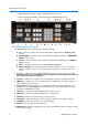
AD2089 Keyboard Controller • selectable speaker volume - enables eight different volume levels • auto focus/auto iris capability - supported when used with DeltaDome units AD2089 Keyboard Overview The AD2089 keyboard is comprised of the following elements: A Site - shows the number of the site entered with the keypad when the SITE key (Sk) is pressed. B Monitor/DVMS - shows the number of the monitor or DVR entered when the MON (Mk) or DVMS key is pressed.
AD2089 Keyboard Controller Multi-Function Keys 12 OFF/Page Left key/ Stop - turns off auxiliary device in Monitor Operate mode. Displays page to the left in Menu mode. In Playback Operate mode, DATE allows you to select a specific date for playback. On the Numbers Keypad, enter a 4-digit date (mmdd) and press DATE. As a shortcut, you can enter a 2-digit date (dd). 13 ON/Page Right key/ Record - turns on auxillary device in Monitor Operate mode. Displays place to the right in Menu mode.
Connection and Setup of the AD2089 Connection and Setup of the AD2089 This chapter describes the power and data connections between the AD2089 keyboard and the switching system being used. It also describes the setup of communications protocols and other keyboard parameters. Additionally, it describes built-in test procedures used to verify the operational integrity of the keyboard.
Connection and Setup of the AD2089 Connections for Cable Distance of Seven Feet or Less For switching system connections where keyboard-to-system cable distance is seven feet or less, make the following connections using the jumpers included with the dual terminal block J1 Pins J2 Pins 4 (rcd) ⇐ 5 (xmit) 5 (xmit) ⇐ 4 (rcd) 7 (ground) ⇐ 7 (ground) After connecting the jumpers, connect one of the seven foot modular cables from the J2 (system) jack of the dual terminal block, to the appropriate RS-232
Connection and Setup of the AD2089 Installation Precautions The keyboard unit is susceptible to high electrostatic discharge potentials. Care should be taken to locate the unit so as to reduce the likelihood of accidental contact with ESD potentials, such as walking on a carpet under very dry conditions. Should accidental contact occur, and the keyboard unit experiences loss of camera control, momentarily remove power to the unit.
Connection and Setup of the AD2089 Keyboard Setup The AD2089 keyboard communicates via RS-232 protocol. Keyboard setup up the keyboard involves setting the keyboard's baud rate, LED brightness, speaker volume, and PTZ motion control.
Connection and Setup of the AD2089 2 To change the currently displayed volume level, cycle through the levels using the NEXT or LAST keys to move in forward or reverse direction respectively. Each time the level changes, a short tone sounds indicating the new level. 3 When the appropriate level appears in the ENTER display, press the PROG key to save the selection.
Connection and Setup of the AD2089 Built-in Keyboard Operations Test CAUTION ! The following procedures expose internal electrical components and should be performed by qualified service personnel only. The AD2089 has built-in test capability to verify the operational integrity of the unit's hardware and firmware.
Connection and Setup of the AD2089 Speaker Test The speaker test performs an audible check of the keyboard's speaker. A series of audio tones step through the frequency range of the speaker. During this test the CAMERA display shows the message "SOUND". The speaker test is repeated automatically, until the test switch button is pressed to advance to the LED lamp test. LED Lamp Test The LED lamp test simultaneously illuminates all segments of all LEDs in the four keyboard display sections.
Connection and Setup of the AD2089 pan speed (1-8) pan direction (left or right) tilt speed (1-8) tilt direction (up or down) Enter Display (Joystick in Motion) 8 L 1 d • From left to right, the first digit represents the pan speed. Speed is directly proportional to the distance from the joystick’s center position. “1” represents the slowest pan speed, and is therefore the position closest to the center. “8” represents the fastest pan speed, and is therefore the position furthest from the center.
Connection and Setup of the AD2089 Note The count in the ENTER display includes the keys in the ENTER, MULTI-FUNCTION, and CONTROL sections of the keyboard, as well as the “flip” button on the joystick. To verify proper operation, each key on the AD2089 keyboard must be pressed once. The keys can be pressed in any order. When a key is pressed. • An audible tone is sounded, verifying key recognition by the keyboard's microprocessor. • The number in the associated display decrements by one.
Connection and Setup of the AD2089 When the ROM checksum test is completed, the built-in test sequence will return to the speaker test when the test switch button is pressed. To exit the built-in test mode, unplug the wall transformer, remove the test jumper from the dual terminal block, return the jumpers to their original positions, re-connect to the system, and then replug the transformer.
Using the AD2089 in Operate Mode Using the AD2089 in Operate Mode This chapter describes how to call cameras to view on workstation monitors, and explains how to control the movement of pan/tilt cameras, and how to zoom, focus, and adjust the iris of a camera lens. The chapter discusses how to run tours, patterns, and macros, and how to call a salvo. There is also an explanation on how to select a DVR and control the various DVR functions.
Using the AD2089 in Operate Mode • To select Monitor mode, press the MON key. If the user does not enter a number prior to pressing either the DVMS or Monitor keys, the keyboard “remembers” the number of the last DVMS or monitor selected prior to toggling to the alternate mode. Monitor Mode Operations (keyswitch in “operate” position) Selecting Monitors Workstation monitors display the video from the cameras and domes installed in local and/or satellite facilities.
Using the AD2089 in Operate Mode The AD2089 joystick controls the panning and tilting of cameras connected to the switching system. As the joystick is moved to the left or right, and is moved towards or away from the operator, the camera will pan and/or tilt accordingly. For cameras with variable speed pan/tilt capability, camera movement speed is proportional to the positioning of the joystick. The further from the stationary center position the joystick travels, the faster the camera will move.
Using the AD2089 in Operate Mode Controlling Camera Flip To “flip” the camera under keyboard control 180× from its current position (for uninterrupted surveillance of subjects who pass directly beneath the camera, press the button on the top of the joystick knob. The flip feature is active with the AD168 system. Note On suitably equipped domes with the auto-flip function turned on, the dome flips automatically when the subject passes directly beneath the camera.
Using the AD2089 in Operate Mode 2 Press the MONITOR/DVMS key to gain control of the monitor. The monitor number will appear in the MONITOR/DVMS display. The ENTER display will clear. 3 Enter the system tour number to be associated with the monitor under control. The tour number will appear in the ENTER display. 4 Press the RUN key, and then press the ACK key within three seconds to run the designated system tour.
Using the AD2089 in Operate Mode A latched auxiliary remains active until it is deactivated using the appropriate off switch. An example of a latched auxiliary is a light. When the auxiliary ON key is pressed (and released), the light is turned on. When the auxiliary OFF key is pressed (and released), the light is turned off.
Using the AD2089 in Operate Mode 3 Press the PATRN key (P-1, P-2, or P-3 appear in the ENTER display) and then press the RUN key. The camera will sequence through the pattern movements once. To repeat a pattern: 1 Follow the procedure described immediately above to run a pattern. 2 After pressing the PATRN key (P-1, P-2, or P-3 appear in the ENTER display), press the ACK key to repeat the pattern. To hold a pattern: 1 Follow the procedure to run a pattern.
Using the AD2089 in Operate Mode Playback Mode Operations (keyswitch in operate position) Selecting DVRs To initiate DVR control, the operator performs the following actions: 1 Type a DVR number of up to four digits on the numeric keypad.
Programming with the AD2089 Programming with the AD2089 This chapter provides step-by-step instructions for keyboard operations performed with the keyswitch in the PROGRAM position. The chapter also includes a discussion of operations available with the keyswitch set in the MENU position. Using the AD2089 in Program Mode When operating with the keyswitch in the PROGRAM position, you can set presets, scratch-pad tours, patterns, and macros. You can also arm and disarm monitors.
Programming with the AD2089 Each time you move the camera in any direction (with zoom, focus, or iris adjustments), you issue a command to the camera. The three patterns for a dome can collectively consist of up to 98 camera commands. There is also a pattern time limit. A single pattern cannot have a duration longer than 400 seconds. How ever many commands have been issued, a pattern will stop recording once the time limit has elapsed.
Programming with the AD2089 Programming Macros There are eight keys on the 2089 keyboard used for macros. A macro performs a sequence of switching system operations by entering a numeric identifier and pressing a single macro key. The macro key caps have user-selected labels which identify locations or general functions. A macro can consist of up to 21 keystrokes. Up to a 1000 different macros can be divided among the eight keys.
Programming with the AD2089 Once programmed, entering a camera number and then pressing the [z] macro key, causes the selected camera to switch to Monitor 1. The symbol “z” represents a monitor and enables a macro quick switch. This macro will enable an operator to reduce the number of keystrokes required to call a camera to a monitor, while also unburdening the operator from having to remember the number of the monitor that has to be addressed.
Programming with the AD2089 After the word “done” appears, pressing any key will remove the word from the LED display. CPU to Keyboard Transfer 1 Set the receiving keyboard and the CPU to the appropriate baud rates. 2 Initiate the 1024 CPU to keyboard transfer by pressing [999] [F2]. The LED display will show the following message: 3 To proceed with the transfer, press ACK. To cancel the action press CLEAR. Pressing any other key will generate a beep indicating an invalid keystroke.
Programming with the AD2089 Using the AD2089 in Menu Mode When the three-position keyswitch is in the MENU position, you are able to view the main menu of the switching system being used.
Programming with the AD2089 28 AD2089 Operator’s Manual
Appendix A: Specifications References RS-232 EIA 232-D CCITT V.24 Keyboard Specifications: Input: AD2089: 9 VAC, 50/60 Hz, 5 W AD2089-1: 8 VAC, 50/60 Hz, 600 mA Power Connection: Wall Transformer Size: 5.25” W x 16.5" L x 1. 6" H Weight: 5.5 lb. (2.
Troubleshooting Appendix B: Troubleshooting Problem 8 No power to keyboard. 9 Check AC outlet 9 Check wall transformer connections 9 Check modular cable connections to keyboard and terminal block 9 Measure transformer output at terminal block 9 Check connection of terminal block to system controller's communication port. 9 Check baud rates for keyboard and system controller. 9 Check DIP switch setting for communications protocol. 9 Run built-in test to verify keyboard operation.
Typical System Connections Appendix C: Typical System Connections AD2089 Keyboards to AD1024 System with Network Client/DVMS Control AD2089 AD2089 31
Typical System Connections AD2089 Keyboard to AD1024 CPU AD2089 AD1024CPU 32 AD2089 Operator’s Manual
Typical System Connections AD2089 Keyboard to AD1024 CPU AD2089 33
Typical System Connections AD2089 Keyboard to AD2150 AD2089 34 AD2089 Operator’s Manual
Typical System Connections AD2089 Keyboard to AD2150 AD2089 35
Typical System Connections AD2089 Keyboard to AD168 AD2089 AD2089 36 AD2089 Operator’s Manual
Typical System Connections AD2089 Keyboard to AD168 AD2089 37
Typical System Connections AD2089 to MegaPower 48 AD2089 KEYBOARD CONNECTIONS OF 7 FEET OR LESS AD2089 KEYBOARD CONNECTIONS GREATER THAN 7 FEET 38 AD2089 Operator’s Manual
Typical System Connections Built-in Test Connection AD2089 7 FOOT MODULAR CABLE WALL TRANSFORMER 39
Software License Agreement Appendix D: Software License Agreement By using the AD2089 software, you accept the terms and conditions of this license agreement. Read this license agreement carefully. 1 General. Software is being licensed to the Customer pursuant to the following terms and conditions, which supplement any purchase or lease agreement (the "Equipment Agreement") between Customer and Sensormatic Electronics Corporation ("SEC").
Software License Agreement Customer will not sell, assign, sublicense or transfer this license or sell or otherwise transfer the Software or Documentation (or any portion thereof) to others.
Software License Agreement the use of the Software or undertake to provide any maintenance, support or information regarding the Software. 7 U.S. Government Restricted Rights. The Software and Documentation are provided with restricted rights. Use, duplication or disclosure by the U.S. Government is subject to restrictions as set forth in subparagraphs (c)(1)(ii) of the Rights in Technical Data and Computer Software Clause of Department of Defense Federal Acquisition Supplement (DFARS) 252.
Monitor Arming Commands Appendix E: Monitor Arming Commands Monitors are armed for alarm call up with codes that specify the following three parameters: 1 The display method (single, dual, or block monitors). 2 The queuing method (sequence or hold) 3 The clearance method (instant, auto, or manual) To arm a monitor with a AD2089 keyboard: 1 Call the monitor to be armed. 2 Turn the keyswitch to the PROGRAM position. 3 Enter the monitor arming code number (see table) 4 Press the F2 key.
Monitor Arming Commands Enable Manual Override 317, F2 Disable Manual Override 318, F2 *= In dual display applications, the1st three-letter acronym is displayed on the hold monitor. The 2nd three-letter acronym is displayed on the sequence monitor.
Macro Key Labels A sheet of pre-printed labels is provided for placement on the AD2089 macro keys. After a macro label is appropriately situated, a clear plastic cover is placed over the macro key and label. Following is a list of currently available macros categorized by application, and their abbreviations as they appear on the labels.
Macro Key Labels 46 AD2089 Operator’s Manual
Macro Programming Worksheets This page provides examples of typical macro sequences. Refer to page 4-3 for a complete description of the sequences described below. The sheet on the following page can be removed from the manual and photocopied as needed to record macros. Each macro sequence starts by entering a number (1-1000) and pressing a macro key. The keystrokes that define the macro are then entered. Up to 21 individual keystrokes are allowed. Each macro is concluded by pressing the macro key again.
Macro Programming Worksheets Macro Programming Workskeet Macro # Macro Name Macro Keystrokes Macro Keystrokes Macro Keystrokes Macro Keystrokes Macro Keystrokes Macro Keystrokes Macro Keystrokes 1 2 3 4 5 6 7 8 9 10 11 12 13 14 15 16 17 18 19 20 21 Note Remove this page and photocopy as needed to record macros. Each macro sequence starts by entering a number (1-1000) and pressing a macro key. The keystrokes that define the macro are then entered. Up to 21 individual keystrokes are allowed.
Glossary A alarm The system's response when a camera input changes from its normal state to its abnormal state (if the system has been configured to respond to such a condition).When an alarm is triggered, the TOUCH TRACKER beeps until you acknowledge the alarm via the Ack button. arming Arming is the process by which a video monitor or monitor block is associated with a specific alarm contact, and is assigned an appropriate monitor arming code.
Glossary F fixed camera A camera which views a scene from a single perspective. A fixed camera cannot pan or tilt, or make automatic lens adjustments. flip To instantaneously position a dome 180× in the opposite direction of where it is currently pointing. focus The process of adjusting the clarity of a scene or an object, as seen through a camera. I input A device such as a smoke detector or twilight sensor that, when configured to do so, can trigger an alarm when it undergoes a change in state.
Glossary M macro A macro is a programmable sequence of keystrokes which allow the operator to execute the keystroke sequence by pressing a numeric entry and a single (macro) key. The 2089 keyboard contains eight macro keys which can be programmed for up to 1000 macro sequences distributed among the eight keys. momentary relay An auxiliary relay that is active as long as its control button is pressed.
Glossary T tilt Up and down camera movement. tour A tour is a sequence of camera scenes viewed on at a time on a video monitor. A monitor tour is a temporary sequence of scenes programmed for a single monitor. A monitor tour can contain up to 64 camera, with a dwell time for each camera. A system tour is a pre-programmed through S³ setup software. 64 system tours can be programmed for callup, either by an operator, or an automatic timed event, to any system monitor at any time.