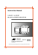
Instruction Manual 9-INCH / 12-INCH BLACK & WHITE MONITOR AMERICAN DYNAMICS Model No.: AD910A SENSORMATIC ELECTRONICS CORPORATION 951 YAMATO ROAD, BOCA RATON, FL 33431 1-800-368-7262 AD912A Please read this manual thoroughly before use, and keep it handy for future reference.
WARNING: TOREDUCE THERISK OF FIRE OR ELECTRIC SHOCK, DONOT EXPOSE THIS PRODUCT TORAIN OR MOISTURE. DO NOT INSERT ANY METALLIC OBJECT THROUGH VENTILATION GRILLS. CAUTION: Explanation of Graphical Symbols The lightning flash with arrowhead symbol, within an equilateral triangle, is intended to alert the user to the presence of uninsulated "dangerous voltage" within the product'senclosure that may be of sufficient magnitude to constitute a risk of electric shock to persons.
IMPORTANT SAFEGUARDS 1. READ INSTRUCTIONS -- All the safety and operating instructionsshould be readbeforetheapplianceisoperated. 2. RETAIN INSTRUCTIONS -- The safety and operating instructionsshould be retained for future reference. 3. CLEANING -- Unplug video monitor or equipment from the wall outlet before cleaning. Do not use liquid cleaners or aerosol cleaners.Useadampclothforcleaning. 4.
FCC COMPLIANCE STATEMENT INFORMATION TO THE USER : THIS EQUIPMENT HAS BEEN TESTED AND FOUND TO COMPLY WITH THE LIMITS FOR A CLASS B DIGITAL DEVICE, PURSUANT TO PART 15 OF THE FCC RULES. THESE LIMITS ARE DESIGNED TO PROVIDE REASONABLE PROTECTION AGAINST HARMFUL INTERFERENCE IN A RESIDENTIAL INSTALLATION. THIS EQUIPMENT GENERATES, USES AND CAN RADIATE RADIO FREQUENCY ENERGY AND, IF NOT INSTALLED AND USED IN ACCORDANCE WITH THE INSTRUCTIONS, MAY CAUSE HARMFUL INTERFERENCE TO RADIO COMMUNICATIONS.
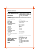
SPECIFICATIONS PICTURE TUBE(Useful screen size) POWER SOURCE 9" Diagonal, 90° Deflection Angle ( 8.7") 12" Diagonal, 90° Deflection Angle (11.6") AC 90 132V 50Hz/60Hz AC 198 264V 50Hz/60Hz CAUTION : Confirm the model number and the power source on the cover page before use.
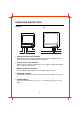
OPERATING INSTRUCTION FRONT 9" 12" 5 5 1 4 1 4 2 3 2 3 1. H-HOLD (horizontal hold) CONTROL When the picture has slanting horizontal bars, rotate the H-HOLD control in either direction until a stationary picture is obtained. 2. V-HOLD (vertical hold) CONTROL When the picture rolls up or down on the screen, adjust V-HOLD control until there is a single steady picture. 3. BRIGHT (brightness) CONTROL Turn clockwise for more brightness and counterclockwise for less. 4.
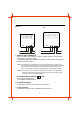
BACK 9" 12" 6 9 6 9 7 8 7 8 6. VIDEO IN / OUT CONNECTOR Connector to the video output of a VCR or another monitor (for loop-through connection) or to a video camera. Loop-through output of the VIDEO IN connector . Connector the video input of another monitor or a VCR. Note: The impedance is automatically set to 75 ohm by the input of a signal on the input connector while operating in a single connection mode.
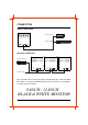
CONNECTION SINGLE CONNECTION to video camera to video output MULTIPLE CONNECTION to video camera to video output Up to 3 monitor can be connected using the loop-through feature of this unit. When this monitor is connected to additional monitors, the same picture can be obtained on all the connected monitors.