COLOR MONITOR ADMCRT15 User Guide Mode d’emploi Bedienungsanleitung Manuale dell'utente Guía del usuario
IMPORTANT SAFETY INSTRUCTIONS 1. 2. 3. 4. 5. 6. 7. 8. 9. 10. 11. 12. 13. 14. Read these instructions. Keep these Instructions. Heed all warnings. Follow all instructions. Do not use this apparatus near water. Clean only with dry cloth. Do not block any ventilation openings. Install in accordance with the manufacturer’s instructions. Do not install near any heat sources such as radiators, heat registers, stoves, or other apparatus (including amplifiers) that produce heat.
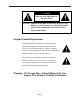
CAUTION RISK OF ELECTRIC SHOCK DO NOT OPEN CAUTION : TO REDUCE THE RISK OF ELECTRIC SHOCK, DO NOT REMOVE COVER (OR BACK). NO USER SERVICEABLE PARTS INSIDE. REFER SERVICING TO QUALIFIED SERVICE PERSONNEL. Graphic Symbol Explanation The lightning flash with arrowhead symbol, within an equilateral triangle, is intended to alert the user to the presence of uninsulated ‘dangerous voltage’ within the product’s enclosure that may be of sufficient magnitude to constitute a risk of electric shock to persons.
IMPORTANT SAFEGUARDS Caution Power source is indicated on the rear of the set. It contains high-voltage parts. If you remove the cover, it may cause fire or electric shock. Do not remove the cover by yourself. (Control switches are at the front of the monitor.) 1. Read Instructions : All the safety and operating instructions should be read before the appliance is operated. 2. Retain Instructions : The safety and operating instructions should be retained for future reference. 3.
8. Accessories : Do not place this monitor on an unstable cart, stand, tripod, bracket or table. The monitor may fall, causing serious injury to a child or adult and serious damage to the appliance. Use only with a cart, stand, tripod. bracket or table recommended by AD(AMERICAN DYNAMICS) or sold with the monitor. Any mounting of the monitor should follow AD(AMERICAN DYNAMICS)’s instructions and should use a mounting accessory recommended by AD(AMERICAN DYNAMICS). 9.
13. Lightning : For added protection for this monitor during a lightning storm or when it is left unattended and unused for long periods of time, unplug it from the wall outlet and disconnect the cable system. This will prevent damage to the monitor due to lightning and power-line surges. 14. Overloading : Do not overload wall outlets and extension cords as this can result in a risk of fire of electric shock. 15.
18. Replacement Parts : When replacement parts are required, be sure the service technician has used replacement parts specified by AD(AMERICAN DYNAMICS) or have the same characteristics as the original parts. Unauthorized substitutions may result in fire, electric shock or other hazards. 19. Safety Check : Upon completion of any service or repairs to this monitor, ask the service technician to preform safety checks to determine that the monitor is in proper operating condition.
Contents IMPORTANT SAFETY INSTRUCTIONS .................Eng-2 IMPORTANT SAFEGUARDS................................... Eng-4 Front Panel Components and Controls ........................ Eng-9 • Using buttons on the front panel ............................Eng-9 Rear Panel Components and Controls ....................... Eng-11 Connections ............................................................... Eng-12 Maintenance................................................................Eng-13 Specifications.......
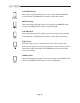
Front Panel Components and Controls Using buttons on the front panel Power Switch On/off switch. If you press this button, the monitor is turned on and the LED of selected input signal is lit. VIDEO Input Selection Switch It selects video and audio input signal. To change input signal, press this button. VOLUME, DATA Control Switch VOLUME key has two functions : • Volume Controls • Data Controls : To change volume, press only this key.
CONTRAST Switch This control adjusts the contrast of the screen image. Press CONTRAST switch and then VOLUME(DATA) switch to control the contrast. BRIGHT Switch This control adjusts the bright of the screen image. Press BRIGHT switch and then VOLUME(DATA) switch to control the bright. COLOR Switch This control adjusts the color intensity of the screen image. Press COLOR switch and then VOLUME(DATA) switch to control the color intensity.
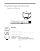
Rear Panel Components and Controls VIDEO LINE IN(A, B) Camera INPUT connector. Input connectors for up to 2 cameras VIDEO LINE OUT(A, B) Monitor OUTPUT connector. VCR IN(VIDEO) VCR INPUT connector. Connect to the VCR. AUDIO LINE IN(A, B) AUDIO INPUT connector. Select corresponding AUDIO input signals AUDIO LINE OUT(A, B) AUDIO OUTPUT connector. AUDIO IN (VCR) VCR AUDIO INPUT connector.
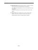
Connections CCD Camera 1 CCD Camera 2 Eng-12
Maintenance If the quality of the picture on the COLOR MONITOR is poor and cannot be improved, inspect all system connections and cable runs. Repairs should be performed by a qualified technician with adequate test equipment and facilities.
Specifications System ADMCRT15 (NTSC/PAL) CRT 15” diagonal, 0.6mm stripe pitch, 90° deflection Video In/Out 2 Channel Input/2 Channel Output. VCR INPUT 1.0Vp-p BNC jack Audio In/Out 2 Channel Input/2 Channel output. VCR Input RCA jack Power Source Control range of main section 100V~250V or “Indicated on the rear of the MONITOR set” Power Consumption 50W Dimensions (W x D x H) 365mm x 391mm x 342mm (without packing) Weight about 16.
COLOR MONITOR ADMCRT15 Mode d’emploi
ATTENTION RISQUE DE DECHARGE ELECTRIQUE NE PAS OUVRIR ATTENTION : POUR REDUIRE LE RISQUE DE DECHARGE ELECTRIQUE, NE RETIREZ PAS LE CACHE (NI LE PANNEAU ARRIERE). AUCUNE PIECE NE PEUT ETRE REPAREE PAR L’UTILISATEUR. ADRESSEZ-VOUS AU PERSONNEL QUALIFIE POUR LE DEPANNAGE.
CONSIGNES IMPORTANTES Attention Le point d’alimentation est indiqué à l’arrière de l'appareil. Il contient des pièces sous haute tension. Si vous retirez le couvercle, un incendie ou une décharge électrique risque de se produire. Ne retirez pas vous-même le couvercle. (Les boutons de commande sont situés à l'avant du moniteur). 1. Lisez les consignes : Vous devez prendre connaissance de toutes les consignes de sécurité et d’utilisation avant la mise en marche de l’appareil. 2.
8. Accessoires : Ne placez pas ce moniteur sur un chariot, un socle, un trépied, une console ou une table instable. La chute du moniteur pourrait blesser grièvement un enfant ou un adulte et gravement endommager l'appareil. Utilisez uniquement un chariot, un socle, un trépied, une console ou une table recommandé(e) par le fabricant ou vendu(e) avec le moniteur. Suivez les consignes de AD(AMERICAN DYNAMICS) lors du montage du moniteur et utilisez l'accessoire de montage recommandé par AD(AMERICAN DYNAMICS).
13. Foudre : Afin d’assurer une protection supplémentaire pour le moniteur, débranchez-le de la prise murale et débranchez le connecteur du réseau câblé en cas d'orage ou d'absence et de non-utilisation prolongées. Cela évitera que le moniteur ne soit endommagé par la foudre et par des surtensions des lignes électriques. 14. Surcharge : Ne surchargez pas les prises murales ou les câbles de rallonge car cela crée un risque d’incendie ou de décharge électrique. 15.
18. Pièces de rechange : Lorsque des pièces de rechange sont nécessaires, assurez-vous que le technicien de dépannage utilise des pièces de rechange spécifiées par AD(AMERICAN DYNAMICS) ou des pièces présentant les mêmes caractéristiques que les pièces d'origine. Des substitutions non autorisées peuvent provoquer un incendie, des décharges électriques et d’autres dommages. 19.
Table des matières CONSIGNES IMPORTANTES .................................. Fra-3 Commandes et composants de la façade....................... Fra-8 • Utilisation des boutons du panneau avant ..................Fra-8 Commandes et composants du panneau arrière ......... Fra-10 Branchements.............................................................. Fra-11 Entretien ......................................................................Fra-12 Caractéristiques techniques.........................................
Commandes et composants de la façade Utilisation des boutons du panneau avant Bouton POWER Bouton Marche/Arrêt. Appuyez sur ce bouton pour allumer le moniteur. La LED rouge du signal d’entrée sélectionné s’allume. Bouton VIDEO Input Selection (Sélection d’entrée VIDEO) Il sélectionne le signal d’entrée vidéo et audio. Pour changer le signal d’entrée, appuyez sur ce bouton.
Bouton CONTRAST (Contraste) Ce bouton règle le contraste de l’image affichée à l’écran. Appuyez sur le bouton CONTRAST, puis sur la touche VOLUME (DATA) pour régler le contraste. Bouton BRIGHT (Brillance) Ce bouton règle la brillance de l’image affichée à l’écran. Appuyez sur le bouton BRIGHT, puis sur la touche VOLUME (DATA) pour régler la brillance. Bouton COLOR (Couleur) Ce bouton règle l’intensité de la couleur de l’image affichée à l’écran.
Commandes et composants du panneau arrière VIDEO LINE IN(A, B) Connecteur INPUT (ENTREE) de la caméra. Connecteurs d’entrée de 2 caméras maximum VIDEO LINE OUT(A, B) Connecteur OUTPUT (SORTIE) de la caméra. VCR IN(VIDEO) Connecteur INPUT (ENTREE) du magnétoscope. Connexion au VCR (Magnétoscope). AUDIO LINE IN(A, B) Connecteur AUDIO INPUT (ENTREE AUDIO). Sélectionnez les signaux d’entrée AUDIO correspondants AUDIO LINE OUT(A, B) Connecteur AUDIO OUTPUT (SORTIE AUDIO).
Branchements Caméra 1 à dispositif à transfert de charge Caméra 1 à dispositif à transfert de charge Fra-11
Entretien Si la qualité d’image du MONITEUR COULEUR est mauvaise ou s’il est impossible de l’améliorer, contrôlez tous les branchements et les parcours de câbles. Les réparations doivent être effectuées par un technicien qualifié disposant d’installations et d’équipements de contrôle appropriés.
Caractéristiques techniques Système ADMCRT15 (NTSC/PAL) CRT Diagonale 15”, pas de masque de 0,6 mm ; déviation de 90° Entrée/sortie vidéo Entrée 2 canaux/Sortie 2 canaux. ENTREE MAGNETOSCOPE prise BNC 1,0 Vp-p Entrée/sortie audio Entrée 2 canaux/Sortie 2 canaux.
COLOR MONITOR ADMCRT15 Bedienungsanleitung
VORSICHT GEFAHR DURCH STROMSCHLAG NICHT ÖFFNEN VORSICHT: ZUR VERMEIDUNG EINES ELEKTRISCHEN SCHLAGS DÜRFEN SIE DIE RÜCKWAND AUF KEINEN FALL ABNEHMEN. IM GERÄTEINNEREN BEFINDEN SICH KEINE BEDIENELEMENTE. LASSEN SIE REPARATUREN VON ENTSPRECHEND AUSGEBILDETEM KUNDENDIENSTPERSONAL DURCHFÜHREN. Erklärung der grafischen Symbole Das Blitzsymbol im gleichseitigen Dreieck soll davor warnen, dass im Gerät nicht isolierte gefährliche Spannungen anliegen.
WICHTIGE SICHERHEITSHINWEISE Warnhinweise Das Netzteil befindet sich an der Rückseite des Geräts. Es enthält Hochspannungsbauteile. Das Entfernen der Abdeckung kann zu Bränden oder Stromschlägen führen. Entfernen Sie daher unter keinen Umständen die Abdeckung. (Die Bedienelemente befinden sich auf der Vorderseite des Geräts.) 1. Bedienungsanleitung lesen: Lesen Sie vor der Inbetriebnahme des Geräts aufmerksam die Bedienungsanleitung mit allen Sicherheits- und Bedienungsanweisungen. 2.
8. Zubehör: Stellen Sie dieses Gerät nur auf Gestelle, Ständer, Dreibeine, Konsolen oder Tische, die ausreichende Stabilität bieten. Anderenfalls könnte das Gerät herunterfallen, beschädigt werden und ernsthafte Verletzungen hervorrufen. Verwenden Sie nur Gestelle, Ständer, Dreibeine, Konsolen oder Tische, die von AD(AMERICAN DYNAMICS) empfohlen oder speziell für das Gerät angeboten werden. Bei der Montage des Geräts müssen die Anweisungen von AD(AMERICAN DYNAMICS) befolgt werden.
13. Gewitter: Zum Schutz des Geräts bei einem Gewitter oder während längerer Abwesenheit bzw. Nichtbetrieb trennen Sie das Gerät vom Netz. Trennen Sie außerdem den Kabelanschluss vom Gerät. Auf diese Weise werden Schäden durch Blitzschlag oder Spannungsstöße vermieden. 14. Überlastung: Schließen Sie nicht zu viele Geräte an eine Steckdose oder ein Verlängerungskabel an, da dies zu einem Brand oder elektrischen Schlag führen kann. 15.
18. Ersatzteile: Falls Teile ausgetauscht werden müssen, achten Sie darauf, dass der Kundendiensttechniker die von AD(AMERICAN DYNAMICS) angegebenen Ersatzteile oder solche Ersatzteile verwendet, die die gleichen technischen Eigenschaften wie die Originalteile aufweisen. Der Einbau nicht genehmigter Ersatzteile kann zu einem Brand oder elektrischen Schlag führen oder andere Gefahren bergen. 19.
Inhalt WICHTIGE SICHERHEITSHINWEISE.................... Deu-3 Komponenten und Bedienelemente an der Vorderseite ............................................................ Deu-8 • Verwendung der Tasten auf der Vorderseite des Geräts .........................................Deu-8 Komponenten und Bedienelemente an der Rückseite ............................................................. Deu-10 Anschlüsse ................................................................. Deu-11 Wartung .....................
Komponenten und Bedienelemente an der Vorderseite Verwendung der Tasten auf der Vorderseite des Geräts Netzschalter Mit diesem Schalter wird die Stromversorgung des Monitors ein- und ausgeschaltet. VIDEO-Taste Mit dieser Taste werden Video/Audio-Eingänge ausgew hlt. Um Eingangssignal einzustellen, drücken Sie diese Taste. LAUTSTÄRKETASTEN[VOLUME/DATA] Diese Tasten erfüllen zwei Funktionen: • Lautstärkeregelung: die Lautstärke wie gewünscht einstellen.
Kontrasttaste Drücken Sie diese Taste, um den Bildkontrast einzustellen. Ändern Sie den Wert des Bildkontrastes mit den Lautstärketasten. Helligkeitstaste Drücken Sie diese Taste, um die Bildhelligkeit einzustellen. Ändern Sie den Wert der Bildhelligkeit mit den Lautstärketasten. Farbintensität Drücken Sie diese Taste, um die Farbintensit t des Bildes einzustellen. Ändern Sie den Wert der Bildfarbe mit den Lautstärketasten.
Komponenten und Bedienelemente an der Rückseite VIDEO LINE IN(A, B) Anschluss für den Kameraeingang. Anschlüsse für bis zu zwei Kameras VIDEO LINE OUT(A, B) Anschluss für den Kameraausgang. VCR IN(VIDEO) Anschluss für den Videoeingang. Anschluss an den Videorekorder AUDIO LINE IN(A, B) Anschluss für den Audioeingang.
Anschlüsse CCD Camera 1 CCD Camera 2 Deu-11
Wartung Falls Sie die Bildqualität des Farbmonitors schlecht ist und durch Anpassen der Menüeinstellungen nicht verbessert werden kann, überprüfen Sie alle Anschlüsse und Kabel. Reparaturen sollten ausschließlich von einem Techniker mit entsprechender Ausbildung sowie mit geeigneten Testwerkzeugen und Hilfsmitteln durchgeführt werden.
Technische Daten System ADMCRT15 (NTSC/PAL) Röhrenmonitor Bildschirmdiagonale 15 Zoll, vertikaler Streifenabstand 0,6 mm, Sichtwinkel 90° Videoeingang/-ausgang 2 Eingangskanäle / 2 Ausgangskanäle. VCR Eingang 1,0 Vp-p BNC-Buchse. Audioeingang/-ausgang 4 Eingangskanäle / 1 Ausgangskanäle. VCR Eingang 1,0 Vp-p Chinch-Buchse. Spannungsquelle Die Betriebsspannung beträgt 100–250 V oder ist auf der Rückseite des Geräts angegeben.
COLOR MONITOR ADMCRT15 Guía del usuario
PRECAUCIÓN PELIGRO DE DESCARGA ELÉCTRICA NO ABRIR PRECAUCIÓN: PARA REDUCIR EL PELIGRO DE DESCARGA ELÉCTRICA, NO RETIRE LA CUBIERTA. NO HAY PIEZAS EN EL INTERIOR QUE PUEDA REPARAR EL USUARIO. CONSULTE AL PERSONAL CUALIFICADO DE SERVICIO TÉCNICO.
INSTRUCCIONES DE SEGURIDAD Precaución La fuente de alimentación está indicada en la parte posterior del aparato. Contiene piezas de alto voltaje. Si retira la cubierta, puede producir un incendio o una descarga eléctrica. No retire la cubierta usted mismo. (Los interruptores de control están en la parte frontal del monitor). 1. Lea las instrucciones: antes de manejar el aparato deberán leerse todas las instrucciones de seguridad y de funcionamiento. 2.
8. Accesorios: no coloque este monitor sobre una mesita con ruedas, soporte, trípode o mesa que no sean estables. El monitor podría caerse provocando graves lesiones a niños o adultos y averiándose seriamente. Utilice las mesitas con ruedas, soportes, trípodes o mesas recomendadas por AD(AMERICAN DYNAMICS) o que se venden junto con el monitor. Para montar el monitor deberán seguirse las instrucciones de AD(AMERICAN DYNAMICS) y utilizarse los accesorios de montaje recomendados por AD(AMERICAN DYNAMICS). 9.
13. Tormentas eléctricas: para proteger aún más este monitor durante una tormenta eléctrica o cuando no lo utilice durante largos periodos de tiempo, desenchúfelo de la toma de la pared y desconecte el cable del sistema. Esto evitará que el monitor se dañe por rayos o picos de tensión de la línea eléctrica. 14. Sobrecarga: no sobrecargue las tomas de la pared ni los cables alargadores, ya que esto puede provocar incendios o descargas eléctricas. 15.
18. Piezas de repuesto: cuando se necesiten piezas de repuesto, asegúrese de que el técnico utiliza piezas especificadas por AD(AMERICAN DYNAMICS) o que tengan las mismas características que las piezas originales. Los repuestos no autorizados pueden producir incendios, descargas eléctricas u otros peligros. 19.
Índice INSTRUCCIONES DE SEGURIDAD ........................ Esp-3 Componentes y controles del panel frontal ...................Esp-8 • Utilización de los botones del panel frontal ..............Esp-8 Componentes y controles del panel posterior ............ Esp-10 Conexiones ................................................................. Esp-11 Mantenimiento ........................................................... Esp-12 Especificaciones técnicas ............................................
Componentes y controles del panel frontal Utilización de los botones del panel frontal. Interruptor de corriente Interruptor On/Off. Al pulsar este botón, el monitor se conecta y se enciende el Diodo LED de señal de entrada. Interruptor de Selección Entrada VIDEO Selecciona la señal de entrada vídeo y audio. Pulse este botón, para cambiar la señal de entrada.
Botón de CONTRAST (CONTRASTE) Este control sirve para ajustar el contraste de la imagen. Pulse el botón CONTRAST y a continuación el interruptor VOLUME (DATA). Botón de BRIGHT (BRILLO) Este botón sirve para ajustar el brillo de la imagen. Pulse el botón BRIGHT y luego el botón VOLUME para efectuar el control del brillo. Botón de COLOR Este control sirve para ajustar la intensidad de color de la imagen. Pulse el botón COLOR y a continuación el botón VOLUME (DATA) para controlar la intensidad de color.
Componentes y controles del panel posterior VIDEO LINE IN(A, B) Conector de entrada de la cámara. Conectores de entrada para hasta 2 cámaras. VIDEO LINE OUT(A, B) Conector de salida de la cámara. VCR IN(VIDEO) Conector de entrada del aparato de vídeo. Conexión con el aparato de vídeo. AUDIO LINE IN(A, B) Conector de entrada de audio. Seleccione las señales de entrada de AUDIO correspondientes AUDIO LINE OUT(A, B) Conector de salida de audio.
Conexiones CCD Camera 1 CCD Camera 2 Esp-11
Mantenimiento Si la calidad de la imagen del monitor en color es mala y no puede mejorarla, inspeccione todas las conexiones y cables del sistema. Confíe las reparaciones a un técnico cualificado que disponga de los aparatos de prueba e instrumentos adecuados.
Especificaciones técnicas Sistema ADMCRT15 (NTSC/PAL) CRT diagonal de 15 pulg., distancia entre líneas de 0,6 mm, deflexión de 90° Entrada/salida de vídeo 2 canales de entrada /2 canal de salida. clavija BNC de 1,0 Vp-p para entrada de vídeo Entrada/salida de audio 2 canales de entrada /2 canal de salida. entrada de vídeo clavija RCA Fuente de alimentación La gama de control de la sección principal es de 100V~250V o "según se indica en la parte posterior del MONITOR".
COLOR MONITOR ADMCRT15 Manuale dell'utente
ATTENZIONE RISCHIO DI SCARICHE ELETTRICHE NON APRIRE ATTENZIONE: PER RIDURRE IL RISCHIO DI SCARICHE ELETTRICHE, NON RIMUOVERE IL COPERCHIO (O IL PANNELLO POSTERIORE). ALL'INTERNO NON SONO PRESENTI COMPONENTI RIPARABILI DALL'UTENTE. RIVOLGERSI AL PERSONALE DI ASSISTENZA QUALIFICATO.
NORME DI SICUREZZA Attenzione La tensione di rete è indicata nella parte posteriore del prodotto. Contiene componenti ad alto voltaggio. La rimozione del coperchio può provocare incendi o scariche elettriche. Non rimuovere il coperchio. I comandi sono situati nella parte anteriore del monitor. 1. Leggere le istruzioni: è necessario leggere attentamente tutte le istruzioni riguardanti la sicurezza e il funzionamento prima di utilizzare l'apparecchio. 2.
8. Ventilazione: sul cabinet sono state praticate fessure e aperture per garantire la ventilazione, un funzionamento affidabile del monitor e per proteggerlo dal surriscaldamento. Tali aperture non devono mai essere ostruite, ad esempio appoggiando il monitor su superfici morbide quali, letti, poltrone, divani e simili. Il monitor non deve mai essere posizionato vicino o sopra una fonte di calore.
13. Sovraccarico: non sovraccaricare le prese di corrente o le prolunghe poiché potrebbero verificarsi incendi e scariche elettriche. 14. Inserimento di oggetti e di liquidi: non inserire alcun oggetto nel monitor attraverso le aperture poiché potrebbero entrare in contatto con componenti ad alto voltaggio o provocare cortocircuito in parti che potrebbero incendiarsi o provocare scariche elettriche. Non versare alcun tipo di liquido sul monitor. 15. Assistenza: non tentare di aggiustare il monitor.
17. Parti di ricambio: se occorrono parti di ricambio, verificare che il tecnico utilizzi componenti consigliati da AD(AMERICAN DYNAMICS) oppure che siano dotati delle stesse caratteristiche degli originali. Sostituzioni non autorizzate possono provocare incendi, scariche elettriche o altri rischi. 18. Controllo di sicurezza: al termine della riparazione o del servizio di assistenza, chiedere al tecnico di eseguire alcuni controlli per verificare che il monitor funzioni correttamente.
Sommario IMPORTANTI ISTRUZIONI DI SICUREZZA ........... Ita-3 Componenti e comandi del pannello anteriore .............. Ita-8 • Uso dei pulsanti del pannello anteriore .....................Ita-8 Componenti e comandi del pannello posteriore............Ita-10 Collegamenti ................................................................ Ita-11 Manutenzione............................................................... Ita-12 Specifiche ....................................................................
Componenti e comandi del pannello anteriore Uso dei pulsanti del pannello anteriore Interruttore di accensione Interruttore di accensione/spegnimento. Premendo questo tasto il monitor si accende e il LED del segnale di ingresso selezionato si illumina. Interruttore di selezione dell’ingresso VIDEO Seleziona il segnale di ingresso audio e video. Per modificare il segnale di ingresso, premere questo pulsante.
Tasto CONTRAST Regola il contrasto dell’immagine. Premere questo tasto quindi il tasto VOLUME (DATA) per regolare il contrasto. Tasto BRIGHT Regola la luminosità dell’immagine. Premere questo tasto quindi il tasto VOLUME (DATA) per regolare la luminosità. Tasto COLOR Regola l’intensità del colore dell’immagine. Premere questo tasto quindi il tasto VOLUME (DATA) per regolare l’intensità del colore. Tasto TINT Regola il colore in modo che si avvicini il più possibile al colore naturale.
Componenti e comandi del pannello posteriore VIDEO LINE IN(A, B) Connettore Camera INPUT. Connettori di ingresso per un massimo di 2 telecamere VIDEO LINE OUT(A, B) Connettore Camera OUTPUT. VCR IN(VIDEO) Connettore VCR INPUT. Collegare al VCR. AUDIO LINE IN(A, B) Connettore AUDIO INPUT. Selezionare i segnali di ingresso AUDIO corrispondenti AUDIO LINE OUT(A, B) Connettore AUDIO OUTPUT. AUDIO IN(VCR) Connettore VCR AUDIO INPUT.
Collegamenti CCD Camera 1 CCD Camera 2 Ita-11
Manutenzione Se la qualità dell'immagine del MONITOR A COLORI è scadente e non può essere migliorata, ispezionare tutti i collegamenti del sistema e i cavi esterni. Le riparazioni devono essere eseguite da un tecnico qualificato, dotato di adeguate attrezzature e apparecchiature per eseguire test.
Specifiche Sistema ADMCRT15 (NTSC/PAL) CRT Diagonale da 15", distanza tra linee di pixel di 0,6 mm, 15” diagonal, 0.6mm stripe pitch, 90° deflection Ingresso/uscita video Ingresso canale 2 /Uscita canale 2. INGRESSO VCR 1.0Vp-p jack BNC Ingresso/uscita audio Ingresso canale 2/Uscita canale 2.
Please visit our website for more information www.americandynamics.net É2003 Sensormatic Electronics Corporation. Product specifications subject to change without notice. Certain product names mentioned herein may be trade names and/or registered trademarks of other companies. Part No.