KT-400 Ethernet Four-Door Controller Installation Manual DN1726-0811
KT-400 Ethernet Four-Door Controller Installation Manual Table of Contents Pre-Installation Information ......................................................................................................................... 1 Copyright Information ............................................................................................................................................. 1 Safety Instructions .................................................................................................
Configuring the KT-400 Ethernet Four-Door Controller with the KT-Finder .............................................. 33 Installation Checklist ................................................................................................................................. 37 Inputs and Outputs Assignments Sheet ....................................................................................................
KT-400 Ethernet Four-Door Controller Installation Manual Pre-Installation Information To the Installer: If you are familiar with the installation, you can use the installation checklist on page 37 with the symbol. Copyright Information Copyright © 2008 Tyco International Ltd. and its Respective Companies. All Rights Reserved. All specifications were current as of publication date and are subject to change without notice. EntraPass, Kantech and the Kantech logo are trademarks of Tyco International Ltd.
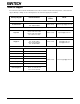
Technical Support For technical assistance with the KT-400 Ethernet Four-Door Controller and other Kantech products, contact technical support, Monday to Friday. See the following table for the technical support phone numbers. Country/Region Phone Numbers Support Hours Email North America Toll Free +888 222 1560 (GMT -05:00) US and Canada Direct: +450 444 2030 Fax: +450 444 2029 8:00 to 20:00 kantechsupport@tycoint.
KT-400 Ethernet Four-Door Controller Installation Manual Compliance Specifications FCC & IC Compliance This device complies with Part 15 of the FCC rules Class A. Operation is subject to the following two conditions: (1) this device may not cause harmful interference, and (2) this device must accept any interference received including interference that may cause undesired operation. This class A digital apparatus meets all requirements of the Canadian Interference Causing Equipment Regulations.
• • • • • • • 1 GB RAM Minimum free hard disk space: 20 GB Color depth: 24-bit (16 million colors), required for Video Integration only Screen resolution: 1024 x 768 Graphic adapter card: 32 MB 48X CD-ROM drive Network Interface card: 10/100 Base-T network adaptor Note: Actual requirements may vary based on your operating system and configuration.
KT-400 Ethernet Four-Door Controller Installation Manual Overview The KT-400 Ethernet Four-Door Controller is designed to meet the highest standards of access control and point monitoring applications. Here are the features of the KT-400 Ethernet Four-Door Controller. Compatible with all EntraPass Special, Corporate and Global Editions The KT-400 Ethernet Four-Door Controller is compatible with all EntraPass Editions v4.
Inputs There are 16 onboard inputs on the KT-400 Ethernet Four-Door Controller. Up to 240 more can be added through the addition of expansion modules, such as the KT-MOD-INP16, for a total of 256 inputs. Each input can be individually configured for one of the following application: • Door contact (4 onboard) • T.
KT-400 Ethernet Four-Door Controller Installation Manual Downloadable Firmware The firmware program can be downloaded from any EntraPass workstation to the KT-400 Ethernet Four-Door Controller. The firmware program, stored in the controller’s flash memory, is upgraded without having to change any parts.
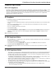
Figure 1: KT-400 Ethernet Four-Door Controller PCB View 8 DN1726-0811
USB-485 Z3C Z4 SPI RS-232 J4 C NO NC Z3 Z3 R C NC INPUT CONFIGURATIONS NC DRY CONTACT INPUT DEFINED OPTION WITH DOUBLE EOL RESISTORS NC TAMPER U28 U24 L5 Y3 U17 DL21 RS232-TX DL20 RS232-RX DL18 COM2-TX DL16 COM2-RX DL14 COM1-TX DL12 COM1-RX DL10 SPI ACTIVE DL9 HEARTBEAT TR2 TR1 P3 C REX Z3 Z11 P6 C Y1 C U5 L2 Z4 P2 U23 U14 R5 C C Z15 Z7 INPUT DOOR 2 REX REX U9 SW1 JP2 JP3 INPUT DOOR 4 U26 CPLD JTAG DOOR Z12 DOOR U25 Y4 Y6 CPU JTAG P1 C
Figure 3: KT-400 Cabinet Model for North America 10 DN1726-0811
KT-400 Ethernet Four-Door Controller Installation Manual System Architecture The KT-400 Ethernet Four-Door Controller can be used through various site applications with EntraPass Special Edition, EntraPass Corporate Edition and EntraPass Global Edition. Applications with EntraPass Special Edition and Corporate Edition with Corporate Gateway. • Over the internet. See Figure 4. • Over RS-232 with a USB-485. See Figure 5. Application with EntraPass Global Edition and a Global Gateway.
Figure 5: USB-485 with EntraPass Special Edition and Corporate Edition with Corporate Gateway Figure 6: VC-485 with EntraPass Global Edition and Global or Corporate Gateway 12 DN1726-0811
KT-400 Ethernet Four-Door Controller Installation Manual Figure 7: Over the internet with a KT-NCC and EntraPass Global Edition Figure 8: Over RS-232 straight from the EntraPass RS-232 COM port DN1726-0811 13
VITAL LED Heartbeat Patterns Communication status and other vital controller parameters can be obtained from VITAL LED heartbeat patterns. It is located near the RS-232 port (COM3), see Figure 1. This information is particularly useful when connecting the controller to the rest of the EntraPass system. The following table lists all conditions along with a brief description. Refer to Table 3, if you must reset or change the communication mode of the KT-400 Ethernet Four-Door Controller.
KT-400 Ethernet Four-Door Controller Installation Manual Technical Specifications Type Description Power input (KT-400) Transformer class 2, IN 120 VAC; OUT 16 VAC, 75 VA Battery back-up (KT-BATT-12) 12 VDC, 7 Ah battery supervised, provides up to 12 hours of operation Operating Temperatures From 2°C to 49°C (35°F to 120°F) indoor use only Humidity Level 0 to 85% (relative humidity non-condensing). Cabinet Dimensions (High-Wide-Deep) 37.59 cm (14.8 in) x 30.48 cm (12.0 in) x 12.57 cm (4.
Electrical Specifications OPEN COLLECTOR OUTPUTS MAXIMUM CURRENT (Typical) LEDs (LED, OUT1 and OUT2) for each door reader 25 mA (each) Buzzer (Buz) for each door reader 25 mA (each) OUTPUTS COMBINED MAXIMUM CURRENT MAXIMUM CURRENT 1 for 12 VDC Auxiliary Power (11.2 to 13.75 VDC) polyswitch protected, shared with SPI expansion port 500 mA 4 for Controlled Readers (11.2 to 13.75 VDC) 500 mA 4 for Controlled Readers 5 VDC 400 mA 4 for Locks (11.2 to 13.
KT-400 Ethernet Four-Door Controller Installation Manual Part number Description DN1475 EntraPass Special Edition, Reference Manual - Spanish version DN1436 EntraPass Corporate Edition, Reference Manual - Spanish version DN1599 EntraPass Global Edition, Reference Manual - Spanish version DN1514 EntraPass Special Edition, Reference Manual - German version DN1598 EntraPass Corporate Edition, Reference Manual - German version DN1597 EntraPass Global Edition, Reference Manual - German version DN16
Models Information • • • • KT-400: Cabinet with one KT-400 for North America, up to three expansion modules can be installed in the cabinet, KT-400-PCB: KT-400 with parts, KT-400-ACC: Accessory kit, KT-400-CAB: Cabinet only for North America, Table 2: Models Bills of Material Item Description KT-400 KT-400-PCB (Notes 1,2) (Note 2) KT-400 PCB 1 1 - - Cabinet 1 - - 1 KT-400-ACC Accessory Kit 1 1 - - Ground wire (PCB to cabinet) 1 1 - - Ground wire (door to cabinet) 1 1 - 1 Tamp
KT-400 Ethernet Four-Door Controller Installation Manual Installing the KT-400 Ethernet Four-Door Controller Preparing to Install the KT-400 Ethernet Four-Door Controller Required to install KT-400 Ethernet Four-Door Controller • • • For North America: AC transformer 120 VAC 60 Hz IN; 16 VAC, 75 VA OUT; class 2 (not included) One battery 12 VDC, 7 Ah (not included) Ground clamp (not included) A visual inspection should be made when unpacking the KT-400 Ethernet Four-Door Controller.
Warning: Controlled door locks may be governed by regulatory bodies and should always be installed according to local regulations. In most instances, there are strict limitations to installing fail-secure devices and fail-safe locking devices such as magnetic locks or other similar locking devices on doors used as emergency exits. Hooking Up Inputs Connect devices to inputs 1 to 16 Resistors for all inputs 5.
KT-400 Ethernet Four-Door Controller Installation Manual Relay Controlled Outputs The KT-400 provides four relay outputs RELAY1 to RELAY4 (3 Amps, 30 VAC/VDC). The KT-400 can be expanded up to 256 controlled outputs when using expansion modules. • The KT-MOD-OUT16 module provides 16 outputs at a maximum of 750 mA per output. • The KT-MOD-REL8 module provides 8 relay outputs at a maximum of 3 Amps per relay.
Connecting the KT-400 Ethernet Four-Door Controller Connecting the VC-485 or the USB-485 to the RS-485 Bus Connect the RS-485 cable to (COM1) + 485 - and the RS-485 signal ground to the 12 VDC AUX - (negative) Controllers are linked together through their RS-485 terminals. The maximum communication loop length is 1.2 km (4,000 ft) using appropriate cabling. The RS-485 communication loop should be wired with Ethernet Category 3 double twisted pair network cable or better.
KT-400 Ethernet Four-Door Controller Installation Manual Connecting the Master Controller to the Host PC via RS-232 Connect RS-232 cable from KT-400 to the PC (maximum length 30 m (100 ft)) If the local master controller is located more than 30 m (100 ft) from the host computer, you must use a VC-485 or USB-485 interface.
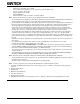
SPI Expansion Port The SPI (Serial Peripheral Interface) expansion port on the KT-400 is used to connect expansion modules, in order to add more inputs and outputs such as relays. The maximum current draw for the SPI expansion port is 500 mA when the 12V AUX terminals are not used. The 6-pin SPI cable must be connected to the SPI IN of the first module. See Figure 9 and Figure 11 for examples of interconnection between the KT-400 and expansion modules.
KT-400 Ethernet Four-Door Controller Installation Manual Important Installation Rules about Expansion Modules Note 1: The maximum current draw must be calculate each time there is a new module added to the SPI chain. Rule 2: The SPI cable, between the KT-400 and the 1st module or between each modules, cannot exceed 1 m (3 ft). Shielded wire should only be used in areas with excessive RF noise of electromagnetic interference.
Figure 10: PCB View of Expansion Modules 26 DN1726-0811
BLU DN1726-0811 WHT GRN YEL Z1 SPI IN - BLK O3 + Pos Z5 C Z6 Z7 C Z8 Z9 O4 O5 C Z10 Z11 O6 + O8 O9 O10 O11 Pos Neg + + OUTPUT DEVICE 5 to 24 VDC up to 750 mA O7 KT-MOD-OUT16 + C CONTACT MOTION DETECTOR Z4 BUZZER O2 C 2007-08 Neg Pos C Z13 O12 O13 Z12 Z14 Z15 EXT O14 O15 PWR INT + C SPI OUT PCA 566-493K EXT PWR 24VDC O16 Z16 Neg OPTIONAL EXTERNAL HIGH POWER SOURCE 5 - 24 VDC + 0801 REV.
Figure 12: Expansion Modules Cabinet for North America 28 DN1726-0811
KT-400 Ethernet Four-Door Controller Installation Manual Troubleshooting Table 3: Reset Types and Descriptions Jumpers Heartbeats Patterns Resets Continuous quick flashing Soft Reset: When JP2 and JP3 are ON, the controller will reset on a) power up, b) pushbutton, or c) EntraPass software 'Manual operator soft reset': • All controller's memory definitions and parameters are verified and kept intact if still valid. • With a corporate gateway, the internal event buffer is maintained if still valid.
Default initialization The KT-400 default initialization or Factory Default DHCP is done at Kantech. The following steps should only be followed if: a) You want to configure the KT-400 with the KT-Finder, see page 33. b) The KT-400 was communicating via the RS-232 port and you have installed a VC-485 or USB-485 to communicate via the RS-485 port. c) The KT-400 was communicating via a VC-485 or a USB-485 interface and you want to communicate directly with the serial (RS-232) port.
KT-400 Ethernet Four-Door Controller Installation Manual KT-400 Ethernet Four-Door Controller Maintenance Recommendations The KT-400 includes a lithium ion rechargable battery (see the KT-400 Ethernet Four-Door Controller PCB View on page 8). This battery must be replaced by a Kantech technician to avoid any risk of explosion. If the Lithium-Ion battery stops working, return the circuit board to Kantech. Do not crush, puncture, open, disassemble or otherwise mechanically interfere with the battery.
Configuring the KT-400 Ethernet Four-Door Controller with the Web Configuration Page This procedure is practical if you want to configure the KT-400 in advance before going on site. Optional Documentation Application Note, Networking Basics, DN1796. Before you start • The detachable Network Configuration Information Sheet is fully completed. • Determine your connection to the KT-400 and choose the appropriate network cable that you need. 1.
KT-400 Ethernet Four-Door Controller Installation Manual Configuring the KT-400 Ethernet Four-Door Controller with the KT-Finder The KT-Finder is an application used to configure the KT-400 over the local area network (LAN) or the wide area network (WAN). It doesn’t require any installation. Important: The KT-Finder application is: • • • C:\Program Files\Kantech\Server_xE\Bin, or on the EntraPass CD-ROM, or available as a free download from http://www.kantech.com 1. Quit all EntraPass applications. 2.
Configuring the KT-400 Ethernet Four-Door Controller with the KT-Finder (continued) 7. Put jumpers on JP2 and JP3. 8. Verify your Network Configuration Information Sheet: • Enter the EntraPass IP address or the Domain name of the EntraPass Gateway. This information must be the same as entered in EntraPass workstation for Devices > Site. • Select Obtain an IP address automatically or Use the following IP address. This information must be the same as entered in EntraPass workstation for Devices > Site. 9.
KT-400 Ethernet Four-Door Controller Installation Manual KT-400 Ethernet Four-Door Controller Network Configuration Information Sheet Please complete one sheet per KT-400 Ethernet Four-Door Controller Company Name: Site Name: LAN or WAN (see other side) Configuration in a Local Area Network (LAN) For more details, refer to the EntraPass Reference Manual. MAC Address: 00:50:F9: ______:______:______ Port (18810 by Default) or _________ IP Address Type: DHCP or Static IP Address: ______.______.______.
Configuration in a Wide Area Network (WAN) EntraPass Site For more details, refer to the EntraPass Reference Manual. EntraPass Special Edition / Corporate Gateway IP Address: ______.______.______.______ Router Public IP Address:______.______.______.______ or Domain name: ____________________________ Port Forwarding Checklist For more details, refer to the EntraPass Reference Manual.
KT-400 Ethernet Four-Door Controller Installation Manual Installation Checklist To the Installer: If you are familiar with the installation, you can use the checklist with the symbol.
Inputs and Outputs Assignments Sheet Doors DOOR 1 CONTACT REX DOOR 2 CONTACT REX DOOR 3 CONTACT REX DOOR 4 CONTACT REX Inputs DOOR Z1 NO or NC EOL, DRY or DEOL REX Z2 NO or NC EOL, DRY or DEOL INPUT Z3 NO or NC EOL, DRY or DEOL INPUT Z4 NO or NC EOL, DRY or DEOL DOOR Z5 NO or NC EOL, DRY or DEOL REX Z6 NO or NC EOL, DRY or DEOL INPUT Z7 NO or NC EOL, DRY or DEOL INPUT Z8 NO or NC EOL, DRY or DEOL DOOR Z9 NO or NC EOL, DRY or DEOL REX Z10 NO or NC EOL, DRY or DEOL IN
KT-400 Ethernet Four-Door Controller Installation Manual Figure 14: KT-400 Cabinet Inner Door Sticker Diagram (North America) Figure 15 DN1726-0811 39
40 DN1726-0811