
Ethernet Four-Door Controller Installation Manual


DN1726-0811
21
KT-400 Ethernet Four-Door Controller Installation Manual
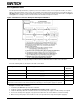
Relay Controlled Outputs
The KT-400 provides four relay outputs RELAY1 to RELAY4 (3
Amps, 30 VAC/VDC). The KT-400 can be expanded up to 256
controlled outputs when using expansion modules.
• The KT-MOD-OUT16 module provides 16 outputs at a maximum of
750 mA per output.
• The KT-MOD-REL8 module provides 8 relay outputs at a maximum
of 3 Amps per relay.
Note: Since the KT-400 maximum output current draw on the SPI
expansion port is 500 mA when the 12V AUX terminals are not
used, an external power supply of 12 VDC, 2 Amps is required
when adding expansion modules to the same KT-400. See
“SPI Expansion Port” on page 24 for additional details
concerning the external power supply requirement for
expansion modules.
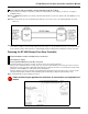
Auxiliary Outputs
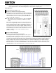
Connect auxiliary outputs to readers and local warning
devices
Auxiliary outputs are used for visual and audible signal. They can
be activated according to input conditions or events and local
alarms. Auxiliary outputs “READER DOOR 1 to 4 - LED” provide
visual feedback of access operation, and auxiliary outputs “READER DOOR 1 to 4 - BUZ” can activate audible warning
devices, such as T-REX or reader buzzer, to signal door alarms.
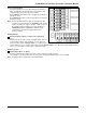
Tamper Protection
Install tamper switch on cabinet
A tamper switch must be installed on the unit to detect unauthorized cabinet opening.
The normally closed tamper switch must be connected to the dedicated tamper input, next to the EGND.
Note: The tamper switch is required for a UL listed installation.