
Specifications


SPEEDDOME ULTRA VII CAMERA DOME INSTALLATION AND SERVICE GUIDE (8200-0184-01, REV. A1)
2 of 41
About the Camera Dome
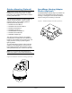
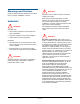
The SpeedDome Ultra VII camera dome (Figure 1)
comes in black or white finish (to blend into
surrounding areas), mounts indoors or outdoors,
and can communicate with the video controller
over a SensorNet 485, RS422, or Manchester
network. The dome consists of a mounting base,
a housing and rotating eyeball assembly.
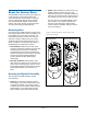
Mounting Base
The housing and eyeball assembly connects to the
base using a twist and lock action, enabling it to be
moved easily from one location to another. The
base attaches directly to a hard or tile ceiling, or
indirectly to walls or ceilings using one of many
optional housings and mounting structures. As
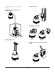
shown in Figure 2, two base types are offered: a
standard base and a base with I/O board.
· Standard Base. With this base, video, data,
and power cables are inserted through the base
and attached to the top of the housing and
eyeball assembly, which is then connected to
the base. A lanyard connects between the base
and the housing and eyeball assembly to
prevent cables from being pulled during
disassembly.
· Base with I/O Board. With this base, video,
data, and power cables are pre-connected to an
I/O PC board. A spring-finger connector on the
board makes electrical contact with the housing
and eyeball assembly as it connects to the
base.
Housing and Eyeball Assembly
The housing and eyeball assembly consists
of the following:
· Housing. The housing contains the dome's
power supply, pan motor, and electronics used
to operate the eyeball. The housing provides
one alarm input and one alarm output using the
standard base, or four alarm inputs and four
alarm outputs using the base with I/O board.
· Eyeball. With a diameter of 120mm (4.75"), the
eyeball contains a camera, tilt motor, and
associated electronics. The eyeball enables the
camera to pan and tilt to track a target moving in
any direction even as it moves under the dome.
Two slot covers in the eyeball facilitate access
to the camera, one of which incorporates an
opening for the camera lens. Remove both
covers to improve ventilation when the dome is
to be used outdoors.
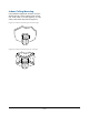
Figure 2. Mounting base and housing and
eyeball assembly
Standard Base
Base with I/O Board