
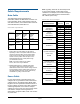
Specifications


SPEEDDOME ULTRA VII CAMERA DOME INSTALLATION AND SERVICE GUIDE (8200-0184-01, REV. A1)
9 of 41
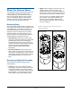
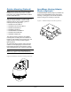
Install/Removal Tool for
Base with I/O Board
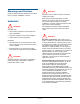
The install/removal tool (Figure 9) enables you to
connect or disconnect the housing and eyeball
assembly from the base with I/O board, and to
attach/detach skirts and bubbles to a top hat
housing, without the need for a ladder. The tool
attaches to a telescopic pole (purchased
separately). See page 20.
CAUTION: Do not use this tool to connect the
dome the standard base.
Figure 9. RHIRT indoor install/removal tool
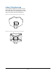
Power-Up Routine
After power is connected to the dome, the dome
performs the following homing routine.
1. After a few seconds, the camera lens tilts up
into the housing and eyeball assembly.
2. The lens tilts downs until it looks at the floor.
3. Eyeball pans slowly.
4. Lens tilts up 90° (home position).
Once the lens is in its home position, you can
then use the controller to call up the camera
and control it.
Synchronizing Domes
To prevent picture rolling when switching from
camera to camera, all domes can be synchronized
to a 50Hz or 60Hz ac source. A V-phase
adjustment at the control console enables the
dome to sync to any line phase.
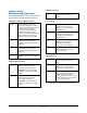
Diagnostic LEDs
If a standard base is used, LEDs in the housing
and eyeball assembly enable you to check for
power and data.
If a base with I/O board is used, LEDs on the
underside of the mounting base enable you to
check for power and data. If an RS422 network is
used, other LEDs on the board indicate that wiring
is correct, reversed, open, or grounded.
RHIRT Removal Tool
Telescopic Pole 08140
by Recreational Water
Products. See page 20
to order.