
Specifications

SPEEDDOME ULTRA VII EIS DAY/NIGHT CAMERA DOME 8200-0184-14, REV. A
INSTALLATION AND SERVICE GUIDE
26 of 37
Disassembling the Dome
CAUTION: Once disassembled, parts of dome
housing and eyeball assembly are "extremely
fragile" and may break. Use extreme care!
This section explains how to remove the following
parts from the camera dome.
• CPU board, page
26
• Power supply, page
26
• Pan motor, page
27
• Slot covers, page
27
• Camera, page
28
• Eyeball, page
29
• Camera/Lens board, page
29
• Tilt motor, page
30.
This section also explains how to update and
reprogram dome software (page
31).
To order parts (authorized users only),
see page
32.
Tools Required
• Phillips-head screwdriver.
• Small slotted screwdriver.
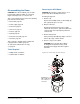
Removing the CPU Board
CAUTION: Electrostatic-sensitive device. Use a
ground strap when handling CPU board.
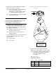
Referring to
Figure 24.
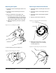
1. Remove cap.
Remove three Phillips-head screws holding cap,
then "gently" lift cap to one side.
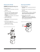
2. Detach connectors.
On CPU board, detach 8-pin power supply
cable from connector P1, pan motor cable from
connector P8, and 14-pin slip ring cable from
connector P2.
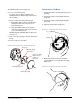
3. Remove CPU board.
Push your finger through large finger connector
hole in cap to pop out CPU board.
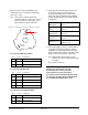
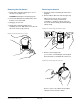
4. Reverse steps to reassemble.
CAUTION: Do not to pinch wires! When
inserting CPU board into housing, avoid
pinching power supply cable wires against
standoffs.
Figure 24. Removing the CPU board
P2
P8
P1
Metal fingers of
ribbon cable must
face contacts of
connector.