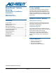
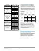
RASI Series SpeedDome Optima Indoor Installation Guide Before performing these steps, ensure power is off and read additional information attached for important details and warnings! ORG YEL 1 Power (Green) ORG GRN YEL BRN WHT BLK 1 R+ R– T+ T– + – Video Output Input 1 Attach cable connectors. Ensure power is off. Manchester NC C NO *AR *AI Terminate Switch RS422 RED WHT BLK Set switches. Example: For address 107, set SW3 to 1, SW2 to •, and SW1 to 7.
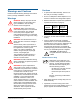
5 6 Secure the housing to a strong structural ceiling member. B C Attach the end of the chain to itself using another S-hook. Close the ends of the S-hook. S Run the chain up into the ceiling and wrap it around a structural member above the housing. 7 Secure the housing to the ceiling. A B Insert housing. Turn each of the four locking screws clockwise to seat the “swing out” mounting clips tightly against the ceiling. Attach the bubble to the housing.
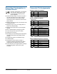
RASO Series SpeedDome Optima Outdoor Installation Guide = Step Prevents Water Intrusion. Before performing these steps, ensure power is off and read additional information attached for important details and warnings! At end of pipe. Sleeve Seal A See A, B, C. 1 C B Line up. Attach cable connectors (in kit 0351-1686-01). Push to line and maintain compresion.
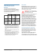
5 Set the dome address and terminate the dome, if necessary. 6 Re-attach the camera/motor assembly to the housing. A Remove lining from adhesive-backed desiccant bag and affix bag, adhesive side down, to the surface of the camera/motor assembly just above the heater assembly. A Attach bubble assembly. A Attach lanyard to stud on flange of housing. Secure with thumbnut. Remove the camera/motor assembly from the housing.
To the Installer SpeedDome® Optima Housing This guide assumes that the outdoor mounting structure to which the housing is attached is in place and that data and power cables have been pulled to the installation site. To install the outdoor mounting structure, see documents shipped with the structure. Continuation of Installation Information RASI Indoor Series RASO Outdoor Series Special Product Features Contents Indoor/Outdoor Housing The dome camera has one alarm input and one SPDT relay.
Cautions Warnings and Cautions • To protect the bubble assembly, leave it in its box until you are ready to install it. Please review the following warnings and cautions before you begin installation or service. • Do not run data/power cables adjacent to or in the same conduit as line voltage mains power. Warnings • Network cable/device requirements (additional requirements are listed on page 8): WARNING! Always use proper lift and safety equipment for the location and type of installation.
Preventing Condensation in Outdoor Domes Connector Pin Assignments GREEN CONNECTOR (POWER) Damage, missing parts, or procedures that most often allow water to enter the housing are as follows (refer to figures opposite): Mounts that allow water to enter the air path.
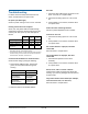
Power Cable Cable Requirements Plenum ceilings. Cable must be rated for plenum and routed through electrical conduit. Use the cable connection cover for conduit termination and cable connections to the dome. Knockouts in the cover accept ½" and ¾" conduit. Data Cable The table below shows requirements for SensorNet, RS-422, and Manchester networks. For more information about communication protocols and cable networks, see Communication Protocols and Cable Networks, 8000-2573-19.
Indoor Dome AC Power Source Worst-Case Meters Low Line V (Feet) 28 VA Transformer 5604-0006-01 117 130 (425) 100 80 (250) 90 60 (200) 50 VA Transformer 5604-0044-01 117 160 (525) 100 100 (325) 90 60 (200) 1-position SensorNet or RS 422 J-Box RJ1SNUD, RS856UD 117 160 (525) 100 100 (325) 90 80 (250) 1-position SensorNet or RS 422 J-Box RJ1SNUD-1, RS856UD-1 240 160 (525) 200 100 (325) 180 80 (250) 117 210 (675) 6-position SensorNet Indoor J-Box 100 130 (425) 90 80 (250)
No video. Troubleshooting 1. Check the video cable and its connection to the dome. If not OK, fix or replace cable. If a failure cannot be easily fixed external to the dome, send the dome to a repair center. 2. Check the iris setting. Open iris or set to auto iris. No power (no LEDs light). Check for power coming in from J-box or controller. Homing routine does not complete. Video rolls when switching cameras.
Illustrated Parts List Not all of the parts, which are shown for clarity, are orderable. Parts are subject to change based on design improvements and availability. Indoor Housing Hard Ceiling Housing Assy. 0400-1246-01 2 1 Housing, Assembly 0400-1246-01 2 Cable Assy., Pigtail 0650-2206-01 1 SPEEDDOME OPTIMA HOUSING CONTINUATION OF INSTALLATION GUIDE 8000-2692-01, REV.
10 5 4 7 8 6 Outdoor Housing 9 Indoor/Outdoor Housing Assy. 0400-1208-01 3 Housing, Aluminum 0500-9175-01 4 Sun Shield 0500-7954-01 5 Top Cover 0500-8001-01 6 Mounting Support 0500-9288-01 7 Nut, Locking, M6, SS (4) 5826-0500-020 8 Washer, FL, STD, M6 (4) 5840-0500-020 9 Gasket 0500-9375-01 10 Lock Nut, 1-1/2 6010-0100-01 11 Screw, M6x40 HHD 5801-4134-520 3 13 12 Indoor/Outdoor, Pigtail Only 0400-1221-01 12 Bracket, Mounting 0500-9185-01 13 Cable Assy.
Camera/Motor Assembly 18 20 19 Tilt Assy. 0400-1207-01/-02 22 21 17 14 Base Assy. 0400-1203-01 15 16 SPEEDDOME OPTIMA HOUSING CONTINUATION OF INSTALLATION GUIDE 8000-2692-01, REV.
Base Assy. 0400-1203-01 14 Bearing, Pan 2510-0040-01 15 Pan Motor Assy. 0400-1240-01 16 PCB, Dome System 0301-1516-01 Tilt Assy. 0400-1207-01 (NTSC), -02 (PAL) 17 Base, Tilt 0500-9110-01 18 Spacer, Tilt (2) 0505-0085-01 19 Tilt Upright (2) 0500-9168-01 20 Timing Belt 2500-0041-01 21 Tilt Motor with Pulley 3501-0028-01 22 PCB, Tilt Sensor 0312-1524-01 SPEEDDOME OPTIMA HOUSING CONTINUATION OF INSTALLATION GUIDE 8000-2692-01, REV.
Color Camera Specifications Type ...................... Interline Transfer ¼" CCD array Scanning system.................................. 2:1 interlace Operation Manual pan speed....................... 1–50° per second Target pan speed ................. 100° per second max. Pan travel ..................360° continuous, no end stop Manual tilt speed ........................ 1–50° per second. Target tilt speed...................... 50° per second max. Horizontal resolution ...............
Alarm input gas discharge tube impulse rated at: Electrical Power Line • 8/20µs Impulse Discharge Current: 10kA Input voltage...................... 24–30Vac, Class 2 LPS • Ten 8/20µs Impulses Discharge Current: 5kA Design tolerance ..................................... 16–36Vac • 33 ohm series resistors Line frequency............................................ 50/60Hz • TVS rated at 5.6V, 40A, 0.1 Joules, 8/20µs impulse Power consumption................................. 15W max.
Alarm Input Provides signal input to dome alarm. Connector.................................... Plug-in Euro-style terminal block 3.81mm Relay Output Provides contact closure output from dome output. Contact type ..............................Form 1-C, NO, NC, and common connections Isolation ............................................................. 1kV Contact material ..................... Gold-clad silver alloy Contact rating .............................. 30Vac or Vdc, 1A Connector...................
Other Declarations Declarations Regulatory Compliance Emissions ...................................... 47 CFR, Part 15 ICES-003 EN55022 Immunity ........................................EN50130-4 (CE) Thank you for using American Dynamics products. We support our products through an extensive and worldwide network of dealers. The dealer, through whom you originally purchased this product, is your point of contact if you have a need for service or support.