
Installation guide


SPEEDDOME OPTIMA HOUSING 8000-2692-01, REV. F
CONTINUATION OF INSTALLATION GUIDE
7 of 18
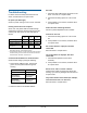
Preventing Condensation in
Outdoor Domes
Damage, missing parts, or procedures
that most often allow water to enter
the housing are as follows (refer to
figures opposite):
Mounts that allow water to enter the air path. If
an older horizontal mount is used, replace it
with a new model or ensure there is ample
slope away from the camera dome and a foam
plug is present
Missing foam plug from entry into the pipe of the
mounting structure
Missing O-ring on cover, or missing sleeve or
seal on end cap assembly
Missing Teflon tape around any housing pipe
threads
RTV or similar sealant covering an air path
Loose nuts (4) at the top of the housing
Heater fans not turning
Bent flange on metal housing that compromises
the gasket seal between the bubble and the
housing
Plugged drain holes in the bubble trim ring
Cracked bubble
Tamperproof screws that are missing or
improperly tightened compromise the gasket
seal between the bubble and the housing
Ensure lanyard is not caught between: a) flange
and trim ring gasket, and b) trim ring and
sunshield.
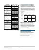
Connector Pin Assignments
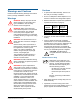
GREEN CONNECTOR (POWER)
Pin Color Description
1 Black 24Vac
2 Red Common
3 White 24Vac
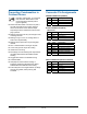
BLACK CONNECTOR (DATA)
Manchester
Pin Color Designation
1-4 Not used.
5 White Manchester (+)
6 Black Manchester (–)
RS-422 / SensorNet
Pin Color Designation
1 Orange RS-422 Data In High (+)
2 Green RS-422 Data In Low (–)
3 Yellow RS-422 Data Out High (+)
4 Brown RS-422 Data Out Low (–)
5 Orange SensorNet (unshielded)
6 Yellow SensorNet (unshielded)
*Color based on composite cable.
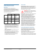
GRAY CONNECTOR (RELAY OUTPUTS)
Pin Color Description
1 N/A Normally Closed
2 N/A Common
3 N/A Normally Open (3.5mA sink)
4 N/A Alarm Return
5 N/A Alarm input (3.5mA sink)