VideoEdge IP Indoor Mini-dome Installation & Operation Guide Version1.
Copyright Under copyright laws, the contents of this manual may not be copied, photocopied, reproduced, translated or reduced to any electronic medium or machine-readable form, in whole or in part, without prior written consent of Tyco International Ltd. © Copyright 2009 and its Respective Companies. All Rights Reserved, American Dynamics 6600 Congress Avenue Boca Raton, FL 33487, U.S.A.
Table Of Contents SAFETY PRECAUTIONS .............................................................................6 1. PRODUCT FEATURES.............................................................................7 1.1 PRODUCT INSTRUCTIONS .....................................................................7 1.2 PRODUCT FEATURES ...........................................................................7 2. DESCRIPTION OF THE FRONT/REAR VIEW .........................................8 2.1 THE FRONT VIEW ....
Installation and Operation Guide 5. Operation Instructions for the Network...............................................27 5.1 MICROSOFT INTERNET EXPLORER ......................................................28 5.1.1 Connecting the IP camera ................................................................................................................28 5.1.2 Change Video Setting.......................................................................................................................30 5.1.
SAFETY PRECAUTIONS All the following safety and operational instructions to prevent harm or injury to the operator(s) or other persons should be read carefully before the unit is activated. WARNING To prevent fire or shock hazard, avoid exposing this unit to rain or moisture. Do not block ventilation openings. Do not place anything on top of the unit that might spill or fall into it.
Installation and Operation Guide 1. PRODUCT FEATURES 1.1 Product Instructions The VideoEdge IP Indoor Mini-dome ADCIPE3312I is a 3-axis IP dome camera with a vandal-proof body for day and night surveillance. With the specific 3-axis mechanical design, this dome camera provides a flexible installation for ceiling or wall mounting and wide angled viewing which pans 360°and tilts 180°. The ADCIPE3312I provides a dual video stream in the MJPEG and MPEG4 formats with up to 30 fps for real-time images.
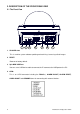
2. DESCRIPTION OF THE FRONT/REAR VIEW 2.1 The Front View 12345678 RESET VIDEO ETHERNET AC 24V -DC 12V+ (PoE) USB SD 1 2 3 4 5 6 7 1. SD CARD slot: This is used for system software updating and archiving / accessing critical images. 2. RESET: Recover to factory default. 3. 5pin MINI USB Port: You can use a USB device cable to connect the IP camera to the USB port on the PC. 4.
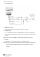
Installation and Operation Guide Alarm wiring diagram: 5. VIDEO OUT Connector: The connector provides the unit’s composite video signals to a monitor. 6. ETHERNET (PoE): This is a standard RJ-45 connector for 10/100 Mbps Ethernet networks. PoE (Power over Ethernet) function: Provides power to the device via the same cable as used for the network connection. NOTE: Please refer to the APPENDIX 6 –PoE Installation Method for more details. 7.
2.2 The USB function By connecting the IP camera with a PC via the USB connector, the IP camera can provide two different functions. 1. Insert an SD card: As a card reader. Insert an SD card into the IP camera, then connect to the PC. You might transfer files between the SD card and the PC. Once you've connected your IP camera to your computer, the Windows system will detect the connection and ask you what you want to do with your SD card.
Installation and Operation Guide 2.3 PoE (Power over Ethernet) These technologies will enable the development of new networked appliances, by providing power as well as data over existing Ethernet cables. The Summary Comparison of PoE Standards (Table 1) is listed as follows. STANDARD Source Voltage IEEE 48 V DC, 802.3af using data protected pairs IEEE 802.3af 48 V DC, using spare protected pairs Table 1.
2.4 Power LED & IR LED Power setting The IR Board: The J1 Jumper: Controls ON/ OFF function of the Power LED LED Power Disable: LED Power Enable (Factory Default): Pin1 & Pin2 short Pin2 & Pin3 short Make short circuits of PIN 1 and PIN 2 to disable the Power LED function. Make short circuits of PIN 2 and PIN 3 to enable the Power LED function.
Installation and Operation Guide The J2 Jumper: Controls ON/ OFF function of the IR LED IR Power Disable (Factory Default): IR Power Enable: Pin1 & Pin2 short Pin2 & Pin3 short Make short circuits of PIN 1 and PIN 2 to disable the IR LED function and the IR LED will not light even when in the night mode. Make short circuits of PIN 2 and PIN 3 to enable the IR LED function and in this situation the IR LED will light in the night mode.
2.5 Lens adjustment Before adjusting the lens, the user has to remove the cover of the dome. 1) Loosen the screws holding the camera mount and then 2) carefully lift the cover up. After all adjustments completion, attach the dome cover to the camera. I. Focus adjustment: (1) Loosen the fixing screws on the Zoom ring and Focus ring. (2) Adjust the angle of view with the Zoom ring and adjust the focus with the Focus ring for the best picture resolution.
Installation and Operation Guide 2.6 Cover Attaching To attach the dome to the base, please do as steps (1) and (2). (1) Note that the protrusion (the convex-shaped fitter) 1 that reaches right up to the edge of the ring on the dome cover must align with the concave 2 on the dome body. The dome cover The dome body (2) Screw the dome cover and the body together.
2.7 Ceiling mounting When mounting the camera in the plywood ceiling, please follow steps (1) to (3). ceiling fix plate plywood ceiling screws*3 (1) Make 3 entry holes in the plywood ceiling as shown above. (2) Install the dome in the ceiling, then attach the supplied “ceiling fix plate” to the camera. (3) Fix the dome to the ceiling using the 3 mounting screws.
Installation and Operation Guide 3. INSTALLATION Please follow the instructions and the diagram below to set up the system. 3.1 UPDATING SYSTEM SOFTWARE If the system software of the IP camera needs to be upgraded, please take the following steps to safely process it. Important: Before carrying out the following procedures, please ensure the SD card is working and the file of the system firmware is intact 1. Format an SD card using the FAT format. 2.
WARNING: 1. Don’t use the NTFS format in step 1. 2. Steps 1 to 3 have to be done on a PC. 3. Make sure the file of UPDATE.BIN is a correct one in step 3, or the IP camera will not work normally after being updated. 4. If the power of the IP camera is suddenly lost in step 8, please remove the SD card first and turn on the IP camera next to test its operation. If the IP camera remains working normally, please go back to step 4; otherwise, please inform your technical support. 5.
Installation and Operation Guide 3.2 IP camera SD card Troubleshooting 1. Check if the SD card position is correct or not. Please refer to the manual for the related information. 2. After powering the IP camera on, correctly insert the SD card, and a little icon of "SD" will show up in the upper-right corner of the monitor screen. If not, it means the device detection has failed. Please contact your technical support and ignore the following steps. 3.
4. Network Configuration 4.1 Cable Connections Please follow the instructions below to connect your IP camera to a computer or a network and to choose a proper RJ-45 cable configuration for connections. Physical specifications of the RJ-45 cable for Ethernet Wire Type Cat. 5 Connector Type RJ-45 Max. Cable Length 100 m Hub Wiring Configuration Straight Through PC Wiring Configuration Straight 4.
Installation and Operation Guide 4.2.2 Set IP Address You need to set an IP address for the unit if the LAN unit isn’t connected to a DHCP server. Otherwise, please follow the instructions given below: Set the IP, MASK and GATEWAY. The following is a sample setting. IP: 192.168.1.X MASK: 255.255.255.0 GATEWAY: 0.0.0.0 NOTE: When only one unit of the IP camera is connected to a computer or LAN, you can freely assign an IP address for the IP camera.
4.3 TCP/IP Communication Software Follow the procedure below to install the TCP/IP communication program in your computer. 1. Open the Start menu from your computer, and select the Settings/Control Panel option. 2. Double click the Network icon to enter the windows.
Installation and Operation Guide 3. Click on the Configuration tag, and check if the TCP/IP is included among the network components list. If the TCP/IP is included, please process section 4.5. If it is not included, please follow section 4.4 to install the TCP/IP. 4.4 TCP/IP Installation During the installation, you will be requested to insert the Windows CD-ROM. After installation, the PC may be restarted.
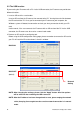
4.5 TCP/IP configuration setting Click Start → Settings → Control Panel → Network. Select TCP/IP, and then click Properties. Before processing the IP camera installation in a WAN, please make sure the Internet connection works properly. If not, please contact your ISP provider. If you are using a DHCP server, please select Obtain an IP address automatically. Any assigned IP address for the connected IP cameras must be in the same class type as the server.
Installation and Operation Guide 4.6 Connection Testing With the previous settings, follow the instructions below to ensure whether you have established the connection successfully. 1. Click Start → Programs → MS-DOS Prompt 2. Enter ping 192.168.1.168, then enter. (See the sample screen below). ** This is the IP address of IP camera that is assigned for the connected IP camera in step2.
successfully established. Please re-check all the hardware and software installations by repeating sections 4.4 and 4.5. If you still can’t establish the connection after rechecking, please contact your dealer. Type Camera IP address If you receive a response as in the sample screen below, you have successfully made the connection.
Installation and Operation Guide 5. Operation Instructions for the Network The Microsoft Internet Explorer in a PC provides the functions of monitoring remote zones or watching recorded data through the TCP/IP protocol. The details are listed as follows. RJ-45 PIN configuration for Ethernet PIN NO. 1. 2. 3. 4. 5. 6. 7. 8. PIN Assignment TX + TX RX + Not Connected Not Connected RX Not Connected Not Connected RJ-45 socket 12345678 Physical specification for Ethernet Wire type Cat.
5.1 Microsoft Internet Explorer 5.1.1 Connecting the IP camera 1. Start up Microsoft Internet Explorer, and then follow the steps below to connect the IP camera. 2. Click on the URL block at the top of the window. 3. Enter the URL address of the IP camera into the URL block and press the “Enter” button to enter the home page. 4. Scroll to the bottom of the page, with its six icons, "Video", "Network", "System", "Application" and "SD card".
Installation and Operation Guide Browsing images from the IP camera The images from the IP camera are displayed on the home page when online with the IP camera. There are also additional settings provided on the home page. MJPEG mode or MPEG4 mode display different display formats on their home page. Homepage of MJPEG mode Homepage of MPEG4 mode Click on the Video button to enter the image-setting page. Click on the Network button to enter the network-setting page.
5.1.2 Change Video Setting Please follow the steps below to change the image setting through the network as necessary. 1. Click on the Video button on the home page to enter the image-setting page. Video setting page of MJPEG mode Video setting page of MPEG4 mode 2. Adjust the image setting including “Device Title”, “Resolution”, “Quality”, “Frame rate” (MPEG4 mode only), “Format”, “Viewer Type” (MJPEG mode only) , and “MJPEG Deinterlace” (MJPEG mode only) as necessary. 3.
Installation and Operation Guide 6. Click on the Day & Night button to enter the Day & Night page. i. Click on the drop-down list to choose the Day & Night mode of “Auto”, “Day mode”, “Night mode” and “Schedule”. ii. Set the values of Focus Adjust and Sensitivity. iii. Click on the Submit button to submit the new Day & Night setting. NOTE: In the “Schedule” mode, you can click the icon to set the Day or Night mode of each hour. “0” means “00:00~00:59”, “1” means “01:00~01:59”, and so on.
7. Click on the Home button to return to the home page while the new image setting acts on the images to effect the desired changes instantly. (If the setting has not been changed by the above steps, any (re)entry onto the home page will find images in their earlier or original setting.) Exchange the image format 1. Select one of the formats then press the Submit button. 2. The IP camera will restart automatically after several seconds.
Installation and Operation Guide 5.1.3 Change the Network Setting Please follow the steps below to change the network setting through the network as necessary. Set the network options and IP address. 1. 2. Click on the Network button in the home page to enter the Network page. The accessible networks here are the “FTP” (for PAL only), “SMTP” (for PAL only), “SNTP”, “DDNS”, “PPPoE”, ”UPnP”, ”IP Filter” and the ”Traffic”. 3.
Description of function keys: IP Address: Enter the 4-byte IP Address in the appropriate blank space (the value in each box may be anywhere between 0 and 255). Every IP camera has to own an IP address to be identified on the network. Netmask: Enter the 4-byte Subnet Mask in the required blank spaces (usually any numbers between 0 and 255). It is used to identify the subnet where the IP camera is sited.
Installation and Operation Guide Change the Network Setting — FTP (MJPEG mode only). Please follow the steps below to change the FTP setting via the network as necessary to upload recording data live. (*FTP function is for PAL version only.) 1. Click on the FTP button at top left to enter the “FTP Server Setting” page. 2. Enter the “FTP Server” address, the “User Name”, and the “Password” of the FTP Server; and set the “File Upload Path” of the image files when necessary. 3.
Change the Network Setting — SMTP (MJPEG mode only). Please follow the steps below to change the SMTP setting through the network as necessary. 1. Click on the SMTP button on the upper left menu to enter the “SMTP Server Setting” page. (*SMTP function is for PAL version only.) 2. Click “My Server Requires Authentication” to checkmark the box and activate the function. 3. Enter the Sender name, DOMAIN NAME of the SMTP server, and set the recipient’s e-mail address as necessary. 4.
Installation and Operation Guide Change the Network Setting — SNTP. Please follow the steps below to change the SNTP setting through the network as necessary. 1. Click on the SNTP button on the upper left menu to enter the “SNTP Server Setting” page. 2. Enter the IP Address of the SNTP server, and choose one of the time zones as and when necessary. 3. Click “Automatically Adjust for Daylight Saving Time Changes” to checkmark the box and activate the function. 4.
Change the Network Setting — DDNS. The “Network” page has, on its upper left, the “DDNS” icon. Please follow the steps below to change the DDNS setting through the network as necessary. 1. Click on the DDNS button on the upper left menu to enter the “DDNS Setting” page. 2. Click “Enable DDNS Function” to checkmark the box and activate the function. 3. Click ”DDNS Type” to open the list of two DDNS modes to choose from: “DynDNS” and “hn”.
Installation and Operation Guide Description of function keys: Enable DDNS Function: Checkmark to activate the function. DDNS Type: Click to open the list of two DDNS modes to choose from: “DynDNS” and “hn”. Click on the “Apply” button and connect this website automatically and enter it. Enter your dynamic IP Address and Email Address. If they are accepted by the website, you will get an Email containing your DDNS Account and DDNS Password in your Email box.
Change the Network Setting — PPPoE. The “Network” page has, on its upper left, the “PPPoE” icon. Please follow the steps below to change the PPPoE setting through the network as necessary. 1. Click on the PPPoE button on the upper left menu to enter the “PPPoE Setting” page. 2. Please read the “PPPoE Troubleshooting” document first, then press “Close’ button. 3. Click on the “PPPoE mode” to activate the function. 4. Enter the PPPoE “Account” and the PPPoE “Password”. 5.
Installation and Operation Guide Change the Network Setting —UPnP. The “Network” page has, on its upper left, the “UPnP” icon. Please follow the steps below to change the UPnP setting through the network as necessary. 1. Click on the UPnP button on the upper left menu to enter the “Universal Plug and Play” page. 2. Click “Enable UPnP” to checkmark the box and activate the function. 3. Enter the UPnP “Max Expired Age”, the “SSDP Port” and the “UPnP Port”. 4.
Change the Network Setting — IP Filter The “Network” page has, on its upper left, the “IP Filter” icon. Please follow the steps below to change the IP Filter setting through the network as necessary. 1. Click on the IP Filter button on the upper left menu to enter the “Network Setting” page. 2. Click “Enable IP Filter” to checkmark the box and activate the function. 3. Select the Default policy. 4. Set the Allow/Deny IP Filter policy and enter its IP address.
Installation and Operation Guide Change the Network Setting —Network Traffic. The “Network” page has, on its upper left, the “Traffic” icon. Please follow the steps below to change the UPnP setting through the network as necessary. 1. Click on the Traffic button on the upper left menu to enter the “Network Traffic” page. 2. Enter the “Maximum Upload Bandwidth” and the “Maximum Download Bandwidth”. 3. Click on the Submit button to submit the new setting. 4.
5.1.4 Change the System Setting Please follow the steps below to change the date and time of the system setting through the network as necessary. Set the Date and Time of the system 1. Click on the System button in the home page to enter the “Date And Time” page (default). 2. Choose one of the three modes shown on the page to set the Date and Time of the system. The three modes are “Set Manually”, “Synchronize With Computer Time”, and “Synchronize With SNTP Server”. 3.
Installation and Operation Guide Change the System Setting — Timestamp. Please follow the steps below to change/add the timestamp through the network as necessary. 1. Click on the Timestamp button on the left side of the “System - Date and Time” page to enter the “System - Timestamp” page. 2. Click “Enable Timestamp” to checkmark the box and activate the function 3. Add or modify any timestamp’s data as necessary. 4. Enter the "Timestamp Color" you have chosen. 5.
Change the System Setting — Users. Please follow the steps below to change/add the users’ authority through the network as necessary. 1. Click on the Users button on the left side of the “Date and Time” page to enter the “Users” page. 2. Add, modify or delete any user’s data as necessary. 3. Click on the Submit button to submit the new user’s settings. 4. Click on the Home button to return to the home page.
Installation and Operation Guide Change the System Setting — Digital I/O. Please follow the steps below to change the Digital I/O through the network as necessary. 1. Click on the Digital I/O button on the left side of the “Date and Time” page to enter the “Digital I/O Setting” page. 2. Mark the “Digital Input” “ON” or “OFF” and the “Digital Output” “ON” or “OFF”. Click your choices to enable. 3. Click on the Submit button to submit the new user’s settings. 4.
Change the System Setting — Audio. Please follow the steps below to change the Audio through the network as necessary. 1. Click on the Audio button on the left side of the “Date and Time” page to enter the “Audio Setting” page. 2. Mark the “Audio” “ON” or “OFF”. 3. Click on the Submit button to submit the new user’s settings. 4. Click on the Home button to return to the home page. NOTE: This setting is for turning the audio of the Camera on/off automatically.
Installation and Operation Guide Change the System Setting — RS485 Setting. Click on the RS485 Setting button on the left side of the “Date and Time” page to enter the “RS485 Setting” page. Description of function keys: Baud rate: Eight different speeds can be used: 2400 baud per second, 4800 baud, 9600 baud, 19200 baud, 28800 baud, 38400 baud, 57600 baud and 115200 baud. Type: Choose one of the types. Device ID: You have the option of using an ID code (any number between 1 and 255).
Change the System Setting — Update Firmware. Please follow the steps below to update the firmware through the network as necessary. 1. Click on the Update button on the left side of the “Date and Time” page to enter the “Update Firmware” page. 2. Click on the “Browse…” button to select the UPDATE.BIN file which was copied into your computer. 3. Click on the “Update” button. NOTE: DO NOT power off the IP camera during firmware update. NOTE: Don’t interrupt the process while the unit is updating itself.
Installation and Operation Guide View the Event Logs. Please follow the steps below to view events through the network as necessary. 1. Click on the Events button on the upper left above to enter the “Event Log” page. 2. Choose one of the three buttons shown on the page to view an event when necessary. The three buttons are titled “First Page”, “Previous 20”, and “Next 20”. Description of function keys: First Page: Previous 20: Next 20: Displays the first page. Displays the previous 20 pages.
5.1.5 Change the Application Setting Please follow the steps below to change the application setting through the network as necessary. Change the Application Setting — FTP Application Setting (MJPEG mode only). Please follow the steps below to change the FTP setting via the network as necessary to upload recording data live. (*FTP function is for PAL version only.) 1. Click on the Application button on the home page to enter the “FTP Application Setting” page (default). 2.
Installation and Operation Guide Change the Application Setting — SD Card Application Setting. Please follow the steps below to change the SD CARD setting via the network as necessary to upload recording data live. 1. Click on the SD card button on the top left to enter the “SD Card Application Setting” page. SD Card setting page of MJPEG mode SD Card setting page of MPEG4 mode You can choose which SD card storage format to use, MJPEG (MJPEG mode only) or AVI. 2.
Change the Application Setting —SMTP Application Setting (MJPEG mode only). Please follow the steps below to change the SMTP setting via the network as necessary. 1. Click on the SMTP button on the left side to enter the “SMTP Application Setting” page. (*SMTP function is for PAL version only.) 2. Enter the attached file number as and when necessary. The maximum number which can be used is 8. 3. Click on the Submit button to submit the new SMTP setting of the recording. 4.
Installation and Operation Guide Change the Application Setting —Language Setting. Please follow the steps below to change the Language setting via the network as necessary. 1. Click on the Language button on the left side to enter the “Language Setting” page. You have an option as to which language to use. The default is “English” 2. Choose your selected language and click "Submit" to set it.
Change the Application Setting —Record Application Enable Setting. Please follow the steps below to change the setting via the network as necessary. 1. Click on the Enable Record button on the left side of the record to enter the “Record Application Enable Setting” page. Record setting page of MJPEG mode 2. Record setting page of MPEG4 mode Click “Enable Record – UPLOAD Via FTP” to checkmark the box and activate the function (*FTP function is for PAL version only). 3.
Installation and Operation Guide Change the Application Setting —Record - Schedule. 1. Click on the Application button on the home page to enter the “Record - Schedule” page. 2. Check/uncheck any/all of the first seven boxes set vertically in the upper half of the “Schedule” page to enable/disable the programmed recording function, and vary the setting of the targeted item while it is enabled. 3. Click on the Submit button to submit the new schedule setting. 4.
Change the Application Setting — Alarm Application Enable Setting. Please follow the steps below to change the setting via the network as necessary. 1. Click on the Enable Alarm button on the left side of the record to enter the “Alarm Application Enable Setting” page. MJPEG mode 2. MPEG4 mode Click “Enable Alarm – Trigger an Alarm When Ethernet Is Lost” to checkmark the box and activate the function. 3.
Installation and Operation Guide Change the Application Setting — Alarm - Motion Detection. Please follow the steps below to enable changes in the motion detection function of the alarm through the network as necessary. Set the motion detection: 1. Click on the Motion Detection button on the left side of the Alarm to enter the “Alarm – Motion Detection” page. 2. Click and drag the mouse across a targeted zone to draw a red rectangle on the image (coordinates provided below).
5.1.6 Change the SD card Setting Please follow the steps below to change the SD card setting through the network as necessary. Change the SD card Setting — FILELIST of MEMORY CARD. Please follow the steps below to change the setting via the network as necessary. 1. Click on the “SD card” button at the bottom of the home page to enter the “Filelist of Memory Card” screen. The page comes in two modes, the JPEG and the AVI (please refer to the “SD card Application Setting Page”). 2.
Installation and Operation Guide 5.1.7 PPPoE & DDNS Using the PPPoE 1. Install the XDSL software (obtained from your ISP dealer) in your PC. 2. Search your IP camera's IP address: you can connect the IP camera and the Video monitor. The monitor screen will show the IP address on its right side. 3. Turn off the DHCP function (of the IP camera) if it is “ON”. NOTE: Use the IE browser to go to the Network Setting page to note the check box at the top of the page.
Test: Go to the Internet. 1. Set your PC to enter the Internet. 2. Desktop → IE browser → Enter the IP camera IP address (the same address as in the PPPoE settings and step 3 above) → You can see the IP camera images. DDNS settings 1. Check your IP camera’s IP address (monitor ) → open your IE browser → Use the address to connect to the IP camera or view the images → Choose the network → Enter “User name : admin” and “Password : 9999” → Click “OK” . 2.
Installation and Operation Guide 5.1.8 The Bandwidth Calculator of the IP camera You can use the calculator to obtain the rough bandwidth throughput for reference. Enter “http://***.***.***.***/calculator.html” into the URL block and press the “Enter” button to enter the calculating page. (The ***.***.***.*** is the URL address of the IP camera accordingly.
6. ADVANCED OPERATION Question 1: How to view the live images of the IP camera via the Microsoft Internet Explorer on the Desktop PCs or the laptop computers in a situation where there are no monitors or television? ◇To get the IP address of the IP camera without a monitor, use one of the following two methods to get the IP address: UPnP and IP function. UPnP: Please refer to APPENDIX 1. IP function: Please refer to APPENDIX 2.
Installation and Operation Guide ◇Set the recording time (the AVI duration) of the SD card 1. Click on the Application button in the home page into the “SD-Card APPLICATION SETTING” page. 2. Choose the AVI Duration from the drop-down list. If you want to record the file into the SD card for 30 seconds, please choose 30 seconds. 3. Click on the Submit button to submit the setting. ◇Use IE to view the recorded files 1.
3. Choose “ON” from the “PPPoE mode” list to activate it. 4. Enter the Account and the Password which are provided from your ISP. 5. Click on the Submit button to submit the setting. NOTE: Please refer to section 5.1.7 for more details. ◇Use the Sub Hostname to view the IP camera 1. Click on the URL block at the top of the PC screen. 2. Enter the DDNS Host Name of the IP camera into the URL block and press the “Enter” button to enter the login page. 3. Enter the user name and fill in the password. 4.
Installation and Operation Guide 7. SPECIFICATIONS Model ADCIPE3312ICN VideoEdge IP Indoor Mini-dome, 3.3-12mm, clear, NTSC, w/PS ADCIPE3312ICPE VideoEdge IP Indoor Mini-dome, 3.3-12mm, clear, PAL, EU Plug, w/PS ADCIPE3312ICPU VideoEdge IP Indoor Mini-dome, 3.3-12mm, clear, PAL, UK Plug, w/PS ADCIPE3312ISN VideoEdge IP Indoor Mini-dome, 3.3-12mm, smoke, NTSC, w/PS ADCIPE3312ISPE VideoEdge IP Indoor Mini-dome, 3.3-12mm, smoke, PAL, EU Plug, w/PS ADCIPE3312ISPU VideoEdge IP Indoor Mini-dome, 3.
LED indicator Power requirement Network / Power indicator DC12V (8.4W) / AC24V / PoE (IEEE 802.af) Temperature 0 – 50℃ Dimensions (mm) Others Approvals 152.9 (D) x 116.3 (H) FCC / CE / RoHS CD x 1 Quick installation manual x 1 Accessories Power adapter x 1 USB connection line x 1 * Specifications are subject to change without notice. * FTP and SMTP functions are for PAL version only.
Installation and Operation Guide APPENDIX 1. –IP camera UPnP How To ® The most troublesome issue when you setup a LANCam is that you have no idea what the IP ® address of this device is. Now LANCam supports the UPnP (Universal Plug and Play) protocol ® which makes it easier for you to examine it; however, it is a pity that Microsoft Windows XP doesn’t start this service by default.
Figure 2 Step 2: When Control Panel appears, double-click the Network Connections icon. The Network Connections dialog box appears. See Figure 3. Figure 3 Step 3: Click on the Protocols tab in the Network Connections dialog box. See Figure 4. Figure 4 Step 4: When the Local Area Connection Properties dialog box shows up, choose Internet Protocol (TCP/IP) and click Properties. See Figure 5.
Installation and Operation Guide Figure 5 Step 5: In the Internet Protocol(TCP/IP) Properties dialog box, choose Use the following IP Address to indicate that you do not wish to use DHCP, and assign IP Address 192.168.1.200 with Subnet mask 255.255.255.0. Click OK when you finish it. See Figure 6. Figure 6 Step 6: Choose Close to finish the modification. See Figure 7.
2. Install UPnP Packets ® As described before, Microsoft Windows XP doesn’t start the UPnP service by default; however, we have to install some packets before we initialize it. The following steps will help you to install them. Step1: From the Start menu, point to Set Program Access and Default, and then click it. See Figure 8 Figure 8 Step 2: When the Add or Remove Programs dialog box appears, click the Add/Remove Windows Components button. See Figure 9.
Installation and Operation Guide Figure 10 Step 4: Check UPnP User Interface, and choose OK. See Figure 11. Figure 11 Step 5: When the original Network Component Wizard dialog box returns, click Next. See Figure12.
Step 6: After about one minute the UPnP installation will be done, and choose Finish to close it. See Figure13. Figure 13 3. Turn on Services After installation, we should turn on the relative services to start the UPnP protocol. The following procedures will teach you how to do it. Step 1: From the Start menu, point to Settings, and then click Control Panel. See Figure14. Figure 14 Step 2: When Control Panel appears, double-click the Administrative Tools icon.
Installation and Operation Guide Figure15 Step 3: Click on the Services icon in the Administrative Tools dialog box. See Figure16. Figure16 Step 4: When the Services dialog box shows up, double click the SSDP Discovery Service icon. See Figure17.
Figure17 Step 5: Choose Automatic in the Startup type, and click OK to start it. See Figure18. Figure18 Step 6: When the Services dialog box appears again, double click the Universal Plug and Play Device Host icon. See Figure19.
Installation and Operation Guide Figure19 Step 7: Choose Automatic in the Startup type, press the Start button, and click OK to start it. See Figure20. Figure20 Step 8: Restart your system.
® 4. Scan LANCams through My Network Place After your installation and starting services, the UPnP protocol will take effect. You can scan all ® LANCams in My Network Place like Figure21 and Figure22 below. Figure21 Figure22 Just double click the UPnP MPEG4 IP camera the video live stream will pop up automatically ® without assigning any IP address in Microsoft Internet Explorer .
Installation and Operation Guide APPENDIX 2. –The ARP function Setting the IP Address The Ethernet interface on the IP camera has a default IP address (192.168.1.168) that most likely needs to be changed to make it work on your local network. You need to acquire a unique IP address (ask your network administrator).
ARP and ping from UNIX or GNU/Linux: 1. Start a shell 2. Type the following as superuser (root): arp -s [or arp -s < MAC address>] ping Example: arp -s 192.168.1.100 00-0C-0C-00-00-01 ping 192.168.1.100 The device responds to the ping in the examples above if the new address was configured. Note, this method will set the IP address permanently. NOTE: The default account and password after the reset are admin and 9999.
Installation and Operation Guide APPENDIX 3. –Register as a DDNS member The DDNS(dynamic domain name system) is a function which is provided by an American company. Please refer to www.dyndns.com. This chapter provides the user with the basic instructions on how to register a free DDNS service. Registering for a DDNS Enter the URL www.dyndns.com. In the upper right-hand corner of the main page, where there is an item, ”Create Account”, as shown in Figure 1.
Figure 2 Figure 3 Click “My Services” to enter the service page. Please click the “Add Host Service” item which is below the ”My Hosts“ item, as shown in Figure 4. Click “Add Host Service”, and its service items will appear. The Add Dynamic DNS Host item helps to add a new DDNS. Each member may have only one free account, and one free account can have only five DDNS. Click Add Dynamic DNS Host to enter the DDNS setting page as shown in Figure 5.
Installation and Operation Guide Figure 4 Figure 5 All we have to set in this page is the “Hostname” item. You can choose a Sub Hostname as s/he likes from the right-hand side of the Hostname’s drop-down list. NOTE: You don’t have to set the “IP Address” in the same format as the camera’s IP Address. It will renew the IP Address automatically. After finishing the setting, please press the “Create Host” button as shown in Figure 5.
Figure 6 84 Installation and Operation Guide
Installation and Operation Guide APPENDIX 4. –MPEG4 Bit Rate Lookup Table of IP camera 1. When frame rate is higher than 15 frames/second (15 is not including): Highest High Medium Low Lowest FULL D1 3 2.5 2 1.5 1 VGA 2.63 2.25 1.75 1.31 0.88 2CIF 1.5 1.25 1 0.75 0.5 Half VGA 1.31 1.13 0.88 0.67 0.44 CIF 0.75 0.63 0.5 0.38 0.25 QVGA 0.66 0.56 0.44 0.38 0.22 ZOOM * 2 3 2.5 2 1.5 1 ZOOM * 3 3 2.5 2 1.5 1 ZOOM * 4 3 2.5 2 1.5 1 2.
APPENDIX 5. –PoE Installation Method Warning: Please follow the steps in this instruction carefully. Connecting these adapters incorrectly may result in damage to your network devices. 1.
Installation and Operation Guide 2. Indoor Mini-dome POWER+DATA IN: Connect a CAT 5 RJ-45 straight- through cable from the POWER+DATA OUT port on the Power over Ethernet Injector. 3. Power over Ethernet Injector POWER+DATA OUT: Provides the data and power to the IP Indoor Mini-dome camera. Connect this port to the POWER+DATA IN port on the POWER IN: Using the supplied 48V power supply, connect to a wall power outlet. IP box camera.
4. Connecting the IP Indoor Mini-dome: please take the following steps: Step 1: Insert one end of a Cat 5 Ethernet RJ-45 cable into the “LIN IN” port of the Power over Ethernet Injector. Connect the other end of the cable to your network switch or PC. Step 2: Plug one end of the Power adapter into the “POWER IN” port of the Power over Ethernet Injector and the other end into your electrical outlet. The installed connection looks the same as in Figure 1.
Installation and Operation Guide APPENDIX 6. –FAQ 1. Can the SD card be removed during recording? A:No, it cannot be removed until the recording comes to a single point. The POWER LED flashing light signals the SD card is operating. The green light indicates the unit is activating. The red light warns the SD card cannot be removed. If the SD card is withdrawn in this mode, the card will break. 2. I’ve set the function of “Motion Detection” but it doesn’t seem to work.