
Owner manual


INSTALLATION INSTRUCTIONS
DURASTAR 30 SERIES LUMINAIRE
American Electric Lighting a division of Acuity Lighting Group, Inc. Conyers, GA
DRAWING NO. B63632 REV D (FRONT)
©2003 ACUITY LIGHTING GROUP, INC.
PART NUMBER 057-70-63632
WARNING
!
DISCONNECT POWER DURING INSTALLATION AND BEFORE SERVICING
TO AVOID THE RISK OF SEVERE OR FATAL ELECTRICAL SHOCK
CAUTION
DO NOT OVER TORQUE
!
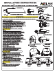
Figure 3
Figure 2
Figure 1
Install lower mast mount cover to upper mast mount
housing. Tighten two bolts to 5 ft-lbs. torque.
"Mast Mount" installation is now complete.
MOUNTING
POSITION
LOCKED
POSITION
REMOVAL
POSITION
STANDARD MAST MOUNT
Wild Life Shield Knockouts
Stair Case Ribs
Indicator Arrow
Voltage Setting
M
UL
T
I
-
48
0V
-
-
3
4
7
V
-
-
2
7
7
V-
-
240V--
2
3
0
V-
-
2
2
0
V
-
-
20
8V
-
-
120V--
Locked Position
Mounting Position
Upper Mast Mount
Lower Mast Mount
Locking Spring
Power Receptacle
Mast Arm
Level Ribs
Fitter Clamp Bolts
Fitter Clamp
Durastar Luminaire Installation/Removal:
Installation:
1. Grasp the luminaire as shown in Mounting Position Detail.
2. Align locking spring as shown in bottom view
of mounting position detail.
3. Rotate the luminaire 20° clockwise, with forward
pressure to compress O-ring. Locking spring should
snap into slot as shown in locked position detail.
Removal:
1. Push locking spring back into removal position.
2. Rotate the luminaire 20° counter clockwise .
3. Pull the luminaire from Mast Mount.
Mast Mount Installation:
For best results the installer should be positioned directly under
and facing the end of the mast arm. If 2" mast arm is used,
remove wild life shield knockouts with pliers and reverse clamp.
Loosen fitter clamp bolts 1/2" for 1 1/4 mast arm or 1 1/4"
for 2" mast arm. Slide mast mount upper onto mast arm and level
on stair case ribs. Level using cross hair ribs if needed.
Torque bolts to 10 ft.-lbs.
Wiring:
Feed the supply wires through the mast arm. Dress them so
they do not interfere with any components and connect them
to the proper terminals on the receptacle. Verify that
the supply voltage is correct as noted on the nameplate.
Refer to the wiring diagram and the data on the nameplate
for connection information and ratings. Rotate the
receptacle to match your supply voltage marking with the
arrow head located in the upper mast mount and press fit
it in place. (Note: Can be placed in lower mast mount if desired)
POWER PLUGS of single voltage luminaires have
been set to match factory wired voltage. POWER
PLUGS of DUAL/MULTI voltage luminaires have been
set to the "MULTI" position for field changes
of voltage. Refer to MULTI-VOLT label, 3-wire
operation label and wiring diagram on inside
wall of luminaire.
Securing Mast Mount Lower:
Locking Spring
CAUTION
DO NOT OVER TORQUE
!
CAUTION
LOCKING SPRING MUST BE
LOCKED AS SHOWN IN FIG. 2
!
TM
DURASTAR SERIES 30
Ignitor