
Installation Sheet


Page 2 of 4 11775 E. 45th Ave. Denver, CO 80239 Ph: 1-800-880-1180 Fax: 303-695-7633
TRULUX
®
RGB + TUNABLE WHITE (IP54)24V
INSTALLATION INSTRUCTIONS
SPTL-RGBTW Series
©2021 American Lighting, Inc. REV2112 www.AmericanLighting.com
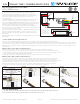
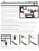
CUTTING & LINKING TAPE LIGHT (SEE FIGURES 2-7):
Do not exceed the maximum tape light run length of 13.1 feet in any single run. Use only the 24V DC power supply provided.
Cut increments are clearly marked on the tape light (every 3.94”). Cutting elsewhere will void warranty. Ensure an even cut along the edge of the copper conductors,
leaving the exposed copper conductor on the piece of tape light to be used, to ensure enough surface area is exposed for snap connector pins to make contact (see
Figure2). When using clamshell connectors, gently scrape o a small amount of the nano-coating that covers each of the 6 conductors on the tape light to ensure a
solid connection.
MAKING A TAPE-TO-TAPE CONNECTION (SEE FIGURES 3-5):
1. Ensure the polarity of the conductors on the two pieces of tape light to be connected are aligned. See Figure 3.
2. Using a tape-to-tape HD connector, open both sides of the connector so the metal teeth inside are exposed. See Figure 4.
3. Peel a small portion of the protective backing from the tape light on the end to be connected, then insert cut tape light end so the
copper pad conductors are aligned with the metal teeth inside.
4. Close snap connector and use pliers to ensure the connector “snaps” through the tape light. See Figure 5.
MAKING A TAPE-TO-WIRE CONNECTION (SEE FIGURES 6-9):
1. Using a tape-to-wire HD connector, follow steps 1-4 from “Making a Tape-to-Tape Connection” above to connect tape light.
2. Ensure polarity of the conductors on the connected piece of tape light and the polarity of the wires align. See Figure 6.
3. Cut desired length of wire from the 15ft reel of wire included being sure to leave approximately 1/2’ on each end to be connected.
4. Separate wires slightly so they fit in the grooves of the snap connector. There is no need to strip the wire. See Figure 7.
5. Insert the cut wire into the slots of the snap connector so the wire is aligned with the metal teeth inside. See Figure 8.
6. Close snap connector and use pliers to ensure the connector “snaps” through the wire. See Figure 9.
FIGURE 2 FIGURE 3
FIGURE 6 FIGURE 7 FIGURE 8 FIGURE 9
FIGURE 4 FIGURE 5
Black
Green
Red
Blue
W White
C White
+24V DC
G
R
B
WW
CW
Black
Green
Red
Blue
W White
C White
+24V DC
G
R
B
WW
CW
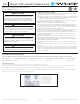
Connect this receiver
to your driver, such as
LED-DR150-24,
matching polarity:
red = (+); black = (-)
FIGURE 1
Pin1:Data+
Pin2:Data-
Pin7:GN D
Pin8:GN D
12345678
DMX
Female
Signal DMX S ignal
Male
DMX Signal
RJ4 5
3
2
V-
V-
V+
V+
1/R-
2/G-
3/B-
4/W1 -
5/W2 -
Back Ente rU pD own
D+
D-
D+
D-
GND
1
3
2
1
12345678
Pin1:GN D
Pin2:D -
Pin3:D +
Pin1:GND
Pin2:D -
Pin3:D +
DMX i n/out
DC Po wer
input
DMX in/ou tDMX i n/out
to 120V AC
24V DC +
GR
RE
BL
WW
CW
12-24V DC
Power Supply
LN
DMX
Master
Control-
ler
D1
D1
GND
+
-
CARE AND MAINTENANCE:
1. Use only a mild soap and water with soft cloth to clean the fixture. Harsh chemicals will damage the finish.
2. Do not wipe the fixture with a rough cloth that may scratch the finish or the lens.
INSTALLING TAPE LIGHT (SEE FIGURE 1):
Disconnect power from source prior to attempting installation. Make all
connections and mount in place prior to providing power to system. Tape
Light includes a 3M adhesive backing: Allow adhesive to cure 24 hours prior to
first use. This product is designed to be mounted to a smooth, clean,
non-moving surface.
1. Determine the placement of tape light and whether there will be cuts, splices,
or jumpers needed. Make any cuts, splices, or jumps prior to moving on to
Step 2. See CUTTING & LINKING TAPE LIGHT on next page for more information
on cutting and/or linking Tape Light. Consider the placement of the power supply
and ensure there is no tension from start of tape light to power supply.
2. Peel the protective backing from the tape light and press the tape light into
place. For best results, once the VHB protective sheet is removed, the tape should
not be repositioned, removed, or re-used.
3. Connect the beginning of the tape light to the REC-DMX, ensuring to match each
wire to the appropriate terminal (black to +, red to red, green to green, etc).
4. Wire the controller to an appropriate LED driver, ensuring to match polarity
(Red +, Black -).
5. Bring 100-277V power to the direct wire power supply, ensuring to match polarity
(Red +, Black -).