
User guide


www.americanlighting.com
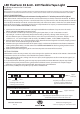
Figure 2: TL-24V-60 cutting instructions
Cut Mark
Copper conductors
Strip away clear plastic to this point to expose copper
conductors to prepare FlexForm for connector.
© American Lighting, Inc. 2012 Made in China
CONTINUED ON REVERSE
RV-1218
LED FlexForm 30 & 60 - 24V Flexible Tape Light
Installation instructions for TL-24V Series
WARNING:
These products may represent a possible shock or re hazard if improperly installed or attached in any way. Products should
be installed in accordance with these instructions, current electrical codes and/or the current National Electric Code (NEC).
LAYOUT CONSIDERATIONS:
Never fold FlexForm or bend past the minimum bending radius of 1” whether powered o or lighted.
Note: The maximum run distance for TL-24V-30 is 32.8 feet (10 meters); 16.4 feet (5 meters) for TL-24V-60. To double
the coverage, consider placing a driver in a central location that can power two runs. The consumption for TL-24V-30 is
2.2 watts/ft; for TL-24V-60, 4.4 watts/ft. Calculate the load(s) and make sure to select a driver that can handle the total
load. For all plug-in drivers, a maximum load less than or equal to 80% of its capacity is recommended for maximum
driver life. See also CONNECTING POWER on reverse.
1. Determine the location of the FlexForm and length needed for the installation. If any cuts are to be made,
follow “CUTTING FLEXFORM” instructions below.
2. If an intersection is involved, plan ahead by starting the layout there. (”L” and “T” connectors are sold
separately, TL-L and TL-T, respectively.) Prepare the mounting surface by dusting and/or cleaning it, so
that the adhesive tape can adhere to the surface, and so that any marks will be easy to locate. Jumpers are also
available in 6” , 12” and 24” lengths, sold separately (TL-JUMP.5, TL-JUMP1, and TL-JUMP2, respectively).
3. Mark the location(s) of any L and T connector(s), then determine the best length for all sections, keeping in mind
that cut marks are located between groups of six LEDs.
4. Determine the type and best location for the power supply in relation to the FlexForm installation to determine
routing of the power cord(s). See also reverse side “CONNECTING POWER” for details regarding hardwire versus
plug-in power supply connection.
5. Mark the location of the beginning of the run where the power connector will be attached.
CUTTING FLEXFORM:
24V FlexForm can be cut every six LEDs, only at the cutting marks specic to TL-24V-30 and TL-24V-60 as shown below.
1. Determine nearest cut mark that is best suited for the specic installation.
2. Using a good pair of scissors, making sure the cut is square, make appropriate cuts for TL-24V-30 (see Figure 1) or
TL-24V-60 (see Figure 2).
3. If a connector will be added on, go to next step to prepare end for connector. Otherwise, skip to step 5 below.
4. Strip back clear plastic protective cover, gently with one blade of scissors, up to outer line to expose copper
conductors. See appropriate illustration below, depending upon type of FlexForm.
5. On back side, carefully cut away 3M
®
tape up to this same outer line.
Figure 1: TL-24V-30 cutting instructions
Inner Lines
Outer
Lines
Outer
Lines
Cut along both inner lines,
removing center material.
Strip away clear plastic to outer line
to expose copper conductors to
prepare FlexForm for connector.
Copper
conductors