American-Lincoln ® Operator's Manual & Parts List Model 7760 Sweeper/Scrubber Beginning with Serial No. 753391 READ THIS BOOK This book has important information for the use and safe operation of this machine. Failure to read this book prior to operating or attempting any service or maintenance procedure to your machine could result in injury to you or to other personnel; damage to the machine or to other property could occur as well.
TABLE OF CONTENTS SPECIFICATIONS ...................................................................................................................... 1-6 MACHINE DIMENSIONS ............................................................................................................. 1-8 STANDARD HARDWARE & TORQUE VALUES ......................................................................... 1-9 HYDRAULIC TORQUE REQUIREMENTS .................................................................................
TABLE OF CONTENTS FILLING THE SOLUTION TANK - NON-RECYCLING (STANDARD) .................................. 1-28 FILLING THE SOLUTION TANK - ESP ............................................................................... 1-28 PRE-START CHECKLIST ................................................................................................... 1-28 BEFORE STARTING THE ENGINE .................................................................................... 1-28 STARTING THE ENGINE ......................
TABLE OF CONTENTS INSPECTING THE AIR FILTER ELEMENT ......................................................................... 1-47 DUST CAP .......................................................................................................................... 1-47 COOLING SYSTEM ............................................................................................................ 1-47 COOLANT LEVEL .....................................................................................................
TABLE OF CONTENTS VACUUM MOTOR & FITTINGS .......................................................................................... 2-79 DUST CONTROL IMPELLER AND FITTINGS .................................................................... 2-80 POWER STEERING UNIT AND FITTINGS ......................................................................... 2-81 MAIN CONTROL VALVE AND FITTINGS ............................................................................ 2-82 CYLINDER CONTROL VALVE AND FITTINGS ...
SAFETY AIR CLEANER ..................................................................................................... 3-28 DEBRIS BASKET OPTION ................................................................................................. 3-29 DETERGENT & SOLUTION TANK, ESP OPTION .............................................................. 3-30 RECOVERY TANK & DETERGENT PUMP, ESP OPTION ................................................. 3-32 LP TANK SYSTEM OPTION ....................................
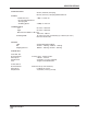
SPECIFICATIONS DIMENSIONS Length Width Height Wheel Base Height with Guard 107.0 Inches - 271.8 Cm. 59.0 Inches - 149.9 Cm. 61.5 Inches - 156.2 Cm. 56.4 Inches - 143.2 Cm. 85.5 Inches - 217.2 Cm. DRIVES Propelling Sweeping Scrubbing Vacuum - Water Pick Up Variable Displacement Pump - Hydraulic Drive Motor (1) Hydraulic Motor (3) Hydraulic Motors (1) Hydraulic Motor HYDRAULIC CONTROL Single Foot Pedal Controls Forward, Neutral, Reverse & Dynamic Braking.
SPECIFICATIONS SWEEPING WIDTH 50 Inch (125.0 Cm.) Sweeping 60 Inch (152.4 Cm.) Sweeping With Side Broom SPEEDS Maximum Travel Recommended Maximum Sweeping And Scrubbing Speed 7 Mph - 11.3 Km./Hr. 4.0 Mph - 6.4 Km./Hr. TURNING RADIUS Left 82 Inches - 208.3 Cm. Right 82 Inches - 208.3 Cm. Minimum Aisle Width for 180° Turn 120 Inches - 305 Cm. Scrubbing Width 54" Inches (137 Cm.) Provided By (3) 17.88 Inch (45.4 Cm.
MACHINE DIMENSIONS 92.0" 233.7 cm. 85.5" 217.2 cm. 61.5" 156.2 cm. 54.5" 138.4 cm. 60.0" 157.5 cm. 56.4" 143.2 cm. 107" 271.8 cm. 27.4" 69.5 cm. 27.0" 68.6 cm. 27.4" 69.5 cm. 59.0" 149.9 cm.
STANDARD HARDWARE & TORQUE VALUES SAE - Grade 8 SAE - Grade 5 Screw Size *6 *8 *10 *1/4 5/16 3/8 7/16 1/2 9/16 5/8 3/4 7/8 1 Grade 5 Plated C 14 27 39 86 15 28 44 68 98 135 239 387 579 F 15 28 43 108 17 31 49 76 110 153 267 - Grade 8 Plated F C 130 151 22 24 40 44 63 70 95 108 138 155 191 216 338 378 545 818 - 410H Stainless C 18 33 47 114 19 34 55 85 - F 20 35 54 132 22 39 62 95 - Type F&T & BT Brass 5 9 13 32 6 10 16 - C 20 37 49 120 - F 23 41 64 156 - Type B, AB 21 34 49 120 - C = Coarse T
HYDRAULIC TORQUE REQUIREMENTS HYDRAULIC TORQUE REQUIREMENTS Refer to the following chart for torque values on all hydraulic hoses and fittings. Nominal SAE Dash Size -3 -4 -5 -6 -8 -10 -12 -14 -16 -20 -24 O-Ring Face Seal End Thread Swivel Size Nut Inch Torque LB-FT * * 9/16-18 10-12 * * 11/16-16 18-20 13/16-16 32-35 1-14 46-50 1 3/16-12 65-70 1 3/16-12 65-70 1 7-16-12 92-100 1 11/16-12 125-140 2-12 150-165 SAE O-Ring Boss End Thread Str.
DECIMAL-METRIC CONVERSION TABLE FRACTION 1 64 0.7938 3 64 0.046875 1.1906 0.0625 1.5875 5 64 0.078125 1.9844 0.09375 2.3813 0.109375 2.7781 0.125 3.1750 0.140625 3.5719 0.15625 3.9688 0.171875 4.3656 0.1875 4.7625 0.203125 5.1594 0.21875 5.5563 0.234375 5.9531 0.25 6.3500 0.265625 6.7469 0.28125 7.1438 0.296875 7.5406 0.3125 7.9375 0.328125 8.3344 0.34375 8.7313 0.359375 9.1281 0.375 9.5250 0.390625 9.9219 0.40625 10.
MACHINE OPERATION P5100/9907 FIGURE 1 YOUR 7760 MACHINE HAS BEEN SHIPPED COMPLETE, BUT DO NOT ATTEMPT TO OPERATE WITHOUT FOLLOWING THESE INSTRUCTIONS. PREPARING THE MACHINE FOR OPERATION 1. Connect and tighten battery cables. 2. Fill the tank with REGULAR GRADE gasoline. (Diesel fuel if equipped with diesel engine.) WARNING Never fill tank while engine is running. Always be sure gasoline container and sweeper are electrically connected before pouring gasoline.
SAFETY INSTRUCTIONS WARNING FOR SAFETY, OBSERVE THE FOLLOWING WARNINGS. FAILURE TO COMPLY MAY CREATE A SERIOUS RISK OF INJURY TO YOU AND OTHERS. THIS MACHINE SHOULD NOT BE USED IN HAZARDOUS LOCATIONS INCLUDING AREAS OF VOLATILE DUST OR VAPOR CONCENTRATIONS. Operators must be trained and qualified to operate this machine. They must also understand the operator’s manual before starting. Use caution when mounting or dismounting the machine particularly on wet slippery surfaces.
OPERATIONS OF CONTROLS AND GAUGES BRUSH ROTATION SWITCH SQUEEGEE SWITCH SCRUB BRUSH LIFT SWITCH BRUSH PRESSURE SWITCH HIGH RECOVERY WARNING LIGHT LOW SOLUTION WARNING LIGHT WATER TEMPERATURE GAUGE HOUR METER FUEL GAUGE OIL PRESSURE GAUGE VOLT METER MAIN BROOM SWITCH SIDE BROOM SWITCH DUST CONTROL SWITCH FILTER SHAKER SWITCH IGNITION SWITCH LIGHT SWITCH HOPPER LIFT HOPPER DUMP DOOR GLOW PLUG SWITCH (DIESEL ONLY) SOLUTION HIGH LIGHT SIDE BROOM LIFT RECYCLING SYSTEM SWITCH HORN PUSH BUTTON DETERGENT L
OPERATIONS OF CONTROLS AND GAUGES GLOW PLUG SWITCH (Diesel) Under no circumstances should any other unauthorized starting aids be used at the same time as Glow Plugs. The Glow Plug Switch is located to the right of the steering column on the front face of the instrument console. Use the following procedure to operate. 1. Before operating the starter motor, press the “GLOW PLUG” button for 20 to 30 seconds. 2. With the “GLOW PLUG” button still depressed, engage the starter motor until the engine starts. 3.
OPERATIONS OF CONTROLS AND GAUGES MAIN BROOM SWITCH The Main Broom Switch is located on the console to the right of the steering wheel in the SWEEPING section. This switch will activate the Main Broom. This switch has two positions “ON” and “OFF”. See Sweeping Broom Lift Control. SIDE BROOM SWITCH (Option For Manual Dump Machines) The Side Broom Switch is located on the console to the right of the steering wheel in the SWEEPING section. This switch will activate the Side Broom.
OPERATIONS OF CONTROLS AND GAUGES WATER TEMPERATURE GAUGE The Water Temperature Gauge is located on the console panel above the steering wheel in the gauge cluster. The gauge is mechanical and activated by a sender in the engine. It displays the engine coolant temperature in farenheight. HOUR METER The Hour Meter is located on the console panel above the steering wheel in the gauge cluster. This meter is activated when the key switch is in the “ignition” position.
OPERATIONS OF CONTROLS AND GAUGES BRUSH ROTATION SWITCH The Brush Rotation Switch is located on the console to the left of the steering wheel in the “SCRUBBING” section. This switch reverses the rotation of the scrub brushes. This switch has two positions “NORMAL” and “REVERSED”. This switch can not be activated unless the Scrub Brush Lift Switch is in the “LOWER” position, the switch will light when activated.
OPERATIONS OF CONTROLS AND GAUGES HOPPER LIFT - (Variable Machines Only) The Hopper Lift Lever is located to the left of the steering wheel on the left side of the drivers compartment. This lever, which is marked “HOPPER”, raises and lowers the debris hopper to ease unloading. WARNING The hopper may drop unexpectedly and cause injury, always engage the safety arm before working under the hopper.
OPERATIONS OF CONTROLS AND GAUGES THROTTLE The throttle control is located to the left of the driver compartment. The engine must be operating at full governed speed of 2150 “no load” RPM (broom control off and machine sitting still), to maintain optimum machine travel speed, hopper loading and dust control. Before turning off the key and stopping the engine, move lever to idle speed. CHOKE LP powered engines do not have a choke. The choke is located to the right of the throttle.
OPERATIONS OF CONTROLS AND GAUGES FORWARD REVERSE P-4690 FIGURE 10 ACCELERATOR & DIRECTIONAL CONTROL PEDAL The accelerator and directional control pedal is located on the floor of the driver compartment, to the right of the brake pedal. The accelerator and directional control pedal controls the machine direction and travel speed. 1. 2. 3. 4. 5. Put foot pressure on the upper portion of the pedal. The machine will move forward.
ESP SYSTEM OPERATING INSTRUCTIONS SOLUTION HIGH WARNING LIGHT DETERGENT FLOW KNOB ON OFF P-4895 RECYCLING SYSTEM ON/OFF SWITCH DETERGENT LOW WARNING LIGHT FIGURE 11 THE ESP RECYCLING CONTROL PANEL THE ESP RECYCLING SYSTEM ON/OFF SWITCH This switch turns the ESP recycling system on and off. SOLUTION HIGH WARNING LIGHT The solution high warning light will come on if the solution tank is too full of water from the recycling system.
ESP SYSTEM OPERATING INSTRUCTIONS THE SCRUBBING SYSTEM - HOW IT WORKS DETERGENT TANK RECOVERY TANK SOLUTION TANK RECOVERY TANK SOLUTION TANK BAFFLE NON-RECYCLING P-4795 FIGURE 13 RECYCLING There are two scrubbing systems available for the 7760 machine, the non-recycling or standard scrubbing system and the recycling or ESP scrubbing system.
ESP SYSTEM OPERATING INSTRUCTIONS THE RECOVERY OR ESP SYSTEM - HOW IT WORKS During the scrubbing process (shown in Figure 16), filtered water from the solution tank is fed to the solution line, where it combines with detergent from the metering pump. This mixture is then fed to the floor where three disc scrubbing brushes work to dislodge soil.
ESP SYSTEM OPERATING INSTRUCTIONS SOLUTION LINE VACUUM SOLTUION TANK SCRUBBING BRUSHES RECOVERY TANK P-5103 AMERICAN-LINCOLN 7760 FIGURE 17 1-25
ESP SYSTEM OPERATING INSTRUCTIONS THE VARIABLE DUMP SWEEPING AND DUST CONTROL SYSTEMS - HOW THEY WORK Variable Dump 7760 machines are equipped with a sweeping and dust control system. Figure 18 shows the highest position for the variable dump.
DUST CONTROL OPERATING INSTRUCTIONS P-5105 FIGURE 19 The debris from sweeping is thrown into the hopper (Figure 19). The baffle system that is built into the variable dump debris hopper is designed to minimize dust in the air while the machine is sweeping. The impeller vacuum fan pulls the lighter dust up and through a baffle system. The Pre-Clean Flap separates the heavier dust particles to an area below the filters. The dust filters capture the lighter dust particles.
OPERATING INSTRUCTIONS FILLING THE SOLUTION TANK NON-RECYCLING or Standard Scrubbing System 1. Make sure the solution control lever is in the “Off” (rear) position. 2. Open the solution tank cover (right hand side). 3. Fill the tank with 100 gallons of water and the correct mixture of American-Lincoln #100 Industrial Cleaner for the job on hand. 4. Close the solution tank cover (right hand side). RECYCLING or ESP System 1. Make sure the solution control lever is in the “Off” (rear) position. 2.
OPERATING INSTRUCTIONS WARNING It is not advised to store the machine in below freezing temperatures unless all fluids have been drained from the detergent solution and recovery tanks and associated systems. When machine has been stored in below freezing temperatures, run engine at not over 1/2 throttle with machine standing still for 5-10 minutes to warm engine and hydraulic oil. POST START CHECKLIST (Engine Running) 1. Check broom pattern. 2. Check squeegee deflection.
OPERATING INSTRUCTIONS NOTE After stopping the engine, perform this post operation checklist. POST OPERATION CHECKLIST 1. Clean debris hopper. 3. Check all flaps for wear, damage and adjustment. 5. Clean solution filter screen (ESP system) 7. Clean recovery tank screens and floats. 9. Check scrub brushes for wear or damage. 11. Fill fuel tank. 2. 4. 6. 8. Check sweeping broom for wear or damage. Drain and clean solution tank (ESP system) Drain and clean recovery tank.
OPERATING INSTRUCTIONS TOW CONTROL SHAFT HOPPER LIFT LEVER HOPPER DOOR LEVER P-5104 P-4183 FIGURE 21 FIGURE 22 DOUBLE LID RECOVERY TANK The Recovery Lid is a double lid. Removing the two hex head bolts, located on the side of the lid can open the lid. The oil cooler and recovery tank vacuum pump are located in the lid. OIL COOLER The oil cooler is located in the recovery tank double lid. TO EMPTY DEBRIS HOPPER 1. Transport or sweep and scrub to the dump site. 2.
SERVICE CHART For service assistance, consult the yellow pages under power sweepers and scrubbers. For best performance, replace worn parts with genuine American-Lincoln parts. EVERY 8 HOURS or DAILY operation check and clean/adjust if necessary: 1. Inspect panel filters for damage and clean. 2. Check engine oil level. 3. Check hydraulic fluid level. 4. Check radiator core for blockage. 5. Check all flaps for wear or damage. 6. Check brooms for wear or damage, adjust as required. 7.
SERVICE CHART 20 2, 25 39 36, 37 11, 34 17 16 4 13, 35 38 26 31 21 9 31 8 15, 33 14 29 3 1, 7, 24 41, 42, 43 12, 40 31 27 28, 30 32 19 AMERICAN-LINCOLN 7760 18 29 5 31 6, 23 1-33
HELPFUL HINTS FOR CLEANING OPERATION SIDE AISLES MAIN AISLE P4134/0001 P-4134 SIDE AISLES FIGURE 23 WARNING Do not turn the steering wheel sharply when the machine is in motion. The sweeper is very responsive to movement of the steering wheel. Do not make sudden turns. Scrub in straight paths. Do not bump posts. Do not scrape the sides of the machine. When the machine is in motion, do not push the directional/speed control pedal all the way forward.
GENERAL MACHINE MAINTENANCE LUBRICATION 6 3 4 4 1 5 P-5114 3 4 2 FIGURE 24 100 Hour Lubrication 1. Lubricate drive wheel swivel, wheel bearings and steering rack guide. 2. Lubricate front wheel bearings. 3. Lubricate all moving joints. 4. Lubricate all 6 DANHOUSER Bushings with NAPA #765-1363 or equivalent anti-seize lubricant. The bush ings are located on the steering, scrub deck lift, squeegee lift, main broom lift, both threaded ends of the throttle cable and the variable dump door cylinders.
GENERAL MACHINE MAINTENANCE HYDRAULICS FILL HYDRAULIC RESERVOIR HOW TO FILL THE HYDRAULIC RESERVOIR 1. Access to the hydraulic reservoir is located beneath the driver’s seat. 2. Open the hydraulic reservoir breather filter cap. 3. Remove any debris that is in the breather filter cap screen. 4. Fill the reservoir until the fluid is at the “FULL” line on the hydraulic fluid sight gauge. The sight gauge is located on the front of the hydraulic reservoir. 5. Close the hydraulic reservoir breather filler cap.
HYDRAULIC SCHEMATIC - VARIABLE DUMP SIDE BROOM VALVE A 1.93 CIR. B SQUEEGEE DECK CYLINDER CYLINDER CONTROL VALVE IN C4 HOPPER CONTROL VALVE C3 SIDE BROOM MOTOR 270 PSI B A C2 2200 PSI 0.159 CIR. SQUEEGEE VACUUM MOTOR SCRUB DECK CYLINDER OIL COOLER LIFT CYLINDER C D C1 OUT B A DUMP CYLINDER POWER STEERING CYLIND ER P 10.0 10.0 Cir. Cir. SCRUB BRUSH MOTORS 4.50 Cir. RETURN BLOCK T 4 3 DUST CONTROL MOTOR 3.05 Cir. 2 4.50 Cir. 1500 PSI WET SWEEP BYPASS VALUE (OPTIONAL) 9.
HYDRAULIC SCHEMATIC - MANUAL DUMP 2 T 3 A T SIDE BROOM VALVE (OPTIONAL) 1 1.93 CIR. B 2200 PSI 0.154 CIR. POWER STEERING CYLINDER L 10.0 CIR. 10.0 CIR. 10.0 CIR. R 3.05 Cir. 4.5 CIR. 1500 PSI P T 2500 PSI 2200 RPM 1.24 CIR 1.02 P5113/0803 CIR 1.
GENERAL MACHINE MAINTENANCE ENGINE Read and follow all the instructions in the Engine Manual Section. Due to the nature of work being done by the machine, extra care must be taken to protect the engine from these elements. Check the oil each day before starting operations. Be sure to check and clean the air cleaner as conditions demand. Do not let the engine become coated with dust and dirt.
GENERAL MACHINE MAINTENANCE MAIN BROOM LEVEL ADJUSTMENT The main broom level is factory set and shouldn’t need adjustment, if the level gets out of adjustment and the broom bristle contact pattern is not an even 2" to 3" (5 to 8 cm.) wide. Adjust the broom arm lift frame (page 68, part number 7-03-04151 and 7-03-04152). The frame is supported by two flange bearings (part number 2-00-04889). These bearings are located inside the broom doors.
GENERAL MACHINE MAINTENANCE 1/16" SET FLAP EVEN WITH FLOOR P-4793 FIGURE 30 FLAPS The urethane and rubber flaps are susceptible to damage and should be inspected regularly and maintained in good condition. The side flaps are adjustable and should be maintained at approximately 1/16" (16 mm.) above the floor. The front and rear flaps have no provision for adjustment. All flaps should be replaced when worn or damaged to such an extent that they couldn’t perform their function.
GENERAL MACHINE MAINTENANCE BRUSH LATCH P-4762 FIGURE 31 SCRUB BRUSH REPLACEMENT 1. Raise the scrub brush deck by pressing the “Scrub Brush” Switch on the instrument panel. 2. Press the brush latches in to release the scrub brush. 3. Remove old scrub brush. 4. Snap new brush into place. COVERS AND LATCHES The covers have been designed to allow access, either by hinge or removal, to all areas of the machine. No maintenance is required. For lubrication of latches see Lubrication Section.
GENERAL MACHINE MAINTENANCE RECYCLING PUMP ESP System The recycling pump is located directly behind and under the recovery tank. The pump is electric and except for daily cleaning of the pump intake screens, it requires no regular maintenance. NOTE Do not run pump dry. The unit depends on the liquid pumped for lubrication. RECYCLING (ESP) PUMP STORAGE Always drain pump for extended storage, especially when freezing temperatures may be encountered.
GENERAL MACHINE MAINTENANCE HOLD DOWN STRAP RECOVERY TANK LID REMOVE 2 SCREWS TO EXPOSE INTERIOR OF RECOVERY TANK LID P-4898 FIGURE 32 BRAKE PEDAL BRAKE LEVER SPRING TENSION KNOB PARKING BRAKE PULL ROD P-4886 FIGURE 33 BRAKE ADJUSTMENT 1. Connect pull rod, preset to 44.5 inch (113 cm.) clevis centerlines, to brake lever then adjust to fit with brake pedal full up and the spring attached. 2. Adjust tension knob on parking brake lever to hold machine on an 8-degree incline.
GENERAL MACHINE MAINTENANCE AIR INTAKE SYSTEM NOTE Monitor the air filter indicator daily The importance of maintaining an air filter cannot be overemphasized. Dirt ingested through improperly installed, improperly serviced, or inadequate air filter elements wears out more engines than long hours of operation. Even a small amount of dirt will wear out a set of piston rings in just a few hours.
GENERAL MACHINE MAINTENANCE A B E D C A B P-4504 FIGURE 35 REMOVING AIR FILTER ELEMENT A. Filter Housing B. Clamp Ring C. Filter Element D. Wing Nut E. Dust Cap FIGURE 36 CLEANING AIR FILTER ELEMENT A. Air Hose B. Filter Element 7. Clean the interior of the air cleaner housing with a damp cloth. Clean the element housing sealing surfaces. 8. Using an air hose, direct dry, clean air maximum 30 PSI up and down pleats on the inside of the filter. Do not rap, tap, or pound dust out of the element.
GENERAL MACHINE MAINTENANCE INSPECTING AIR FILTER ELEMENT A. Bright Light B. Filter Element DUST CAP A. Dust Cap 10. Install the new or cleaned filter element so the fins on the element are at the intake end of the air cleaner. Use care so the fins are not damaged. Tighten the wing nut attaching the element. 11. Install the dust cap with the arrows pointing up. Tighten the clamp ring to hold it in place. Check all intake hose connections for leaks or abrasions. 12.
GENERAL MACHINE MAINTENANCE DRIVE BELTS The drive belt(s) should be properly adjusted at all times. Loose drive belts cause improper alternator, fan and water pump operation, and overheating. Overtightening the belt may result in excessive wear on the alternator and water pump bearings, as well as premature wear on the belt itself. Therefore, it is recommended that proper belt tension be maintained. BATTERY 1. Access the battery through the door located beside the driver’s seat. 2.
GENERAL MACHINE MAINTENANCE LP GAS SYSTEM The propane powered Model 7760 is identical to the “standard” gasoline powered 7760, except that its fuel system has been modified to operate on LP vapor fuel. The LP fuel system consists of several components not found on the gasoline system. The LP fuel system also contains the associated mounting hardware and plumbing for the LP components.
PARTS LIST LEGEND ABBREVIATIONS - SCREWS ADJ ADJ.SP BHM BHS CAPT.SL CAPT.WG FHM FIL.
GENERAL TROUBLESHOOTING PROBLEM Sweeping does not function Poor water pick up at squeegee Water spill from squeegee Lack or suction at rear AMERICAN-LINCOLN 7760 PROBABLE CAUSE REMEDY 1. Dump door closed 1. Open dump door 2. Hopper is raised 2. Lower hopper 3. Hopper switch out of adjustment 3. Adjust hopper switch 1. Side or rear squeegee are worn or damaged 1. Examine squeegee rubber blade for cuts or worn spots. 2. Clogging in water pick up 2. Repair or replace hose and connection 3.
GENERAL TROUBLESHOOTING PROBLEM Poor scrubbing Engine runs, but machine will not move on level ground Machine moves slowly Hydraulic pump making excessive noise 1-52 PROBABLE CAUSE REMEDY 1. Worn scrubbing brushes 1. Inspect brushes. If worn to ½” (1.3cm) or less, replace all 3 brushes 2. Incorrect method of operation 2. Check scrubbing procedures, brush pressure, type of brush, solution flow, & cleaning chemical used. For extreme conditions double scrubbing may be necessary. 3.
FROM CB-4 HR METER & IGNITION CIRCUIT SCHEMATIC DIAGRAM OPTIONS AUTOMATIC OVERRIDE 1 2 3 4 (NO) (OIL) PRESSURESTAT (C) (NC) (NO) (C) (WATER) ALARMSTAT (NC) NOTE: ARE ALARMSTAT AND PRESSURESTAT SHOWN WITH ENGINE OFF.
ORDERING PARTS Parts may be ordered from American-Lincoln authorized distributors. Record the information from the American-Lincoln serial plate to avoid delays in filling your order: MODEL NO. SERIAL NO. Manufactured By AMERICAN LINCOLN TECHNOLOGY ® BOWLING GREEN, OHIO 1. Use the model number, catalog number, and serial number when ordering. 2. Give the part number, description, and quality of parts needed. 3. Give shipping instructions for either freight, UPS, or parcel post.