
User Manual

Rev. 5 75
Operation
Ramping Functions : States and Controls
to be defined and executed (up to 10 segments, each with a unique ramp
rate). The basic charging equation for a superconducting magnet is:
where V is the charging voltage (V), L is the magnet inductance (H), and
di/dt is the ramp rate (A/s). The relationship may also be defined in terms
of a ramp rate in kG/s by the relationship:
where C is the coil constant (or field-to-current ratio) in kG/A, and dB/dt
is the ramp rate expressed in kG/s.
A desired ramp rate should be selected by the user and entered into the
Model 430 Programmer. A Voltage Limit should also be specified that is
greater than or equal to the voltage calculated from the equations above
plus energy absorber voltage (if installed) plus power lead voltage drop
(usually less than 2 V).
Once the ramp rate and Voltage Limit are specified, the Model 430
Programmer provides two modes of ramping: manual and automatic.
Manual ramping will ramp to the Current Limit via manual direction
control by the user. Automatic ramping will ramp to the target field/
current automatically. Automatic ramping can be thought of as a “next
point” operation, whereby the Model 430 determines the appropriate ramp
direction based on the present magnet current and the target value.
Note
You may enter up to 10 digits beyond the decimal point within the
ramping control menus. These extra digits are maintained in the
internal memory of the Model 430 Programmer even though the full
precision is not displayed after entry.
3.12.1 Ramping States and Controls
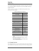
The ramping state may be one of several values as described in Table 3-6.
If the
RAMP / PAUSE key is pressed while ramping, the PAUSED mode
becomes active. To begin automatic ramping, press the
RAMP / PAUSE
key to deactivate the PAUSED mode. If manual ramping is desired, use
either the
INCR. FIELD or DECR. FIELD SHIFT-key for manual control of
ramping up or ramping down, respectively.
Voltage limit and ramp rate may be specified from quickly accessible
SHIFT-key menus from the front panel keypad
1
. The settings for Voltage
VL
id
td
----
=
V
L
C
----
Bd
td
------
=