CPC-3813-MIL 3U CompactPCI 传导加固主板 3U Rugged Conduction-cooled CompactPCI Motherboard Version: C00
声明 本手册包含的内容并不代表本公司的承诺,产品后续相关变更时,本公司 保留对此手册更改的权利,恕不另行通知。对于任何因安装、使用不当而导致的 直接、间接、有意或无意的损坏及隐患概不负责。 订购产品前,请向经销商详细了解产品性能是否符合您的需求。 EVOC是研祥智能科技股份有限公司的注册商标。本手册所涉及到的其他商 标,其所有权为相应的产品厂家所拥有。 研祥智能科技股份有限公司©2011,版权所有,违者必究。未经许可,不得 以机械、电子或其它任何方式进行复制。 欲获更多信息请访问研祥网站:http://www.evoc.com或向研祥技术支持邮箱 support@evoc.com(国际)、support@evoc.
安全使用小常识 1. 产品使用前,务必仔细阅读产品说明书; 2. 对未准备安装的板卡,应将其保存在防静电保护袋中; 3. 在从防静电保护袋中拿出板卡前,应将手先置于接地金属物体上一会儿(比 如 10 秒钟),以释放身体及手中的静电; 4. 在拿板卡时,需佩戴静电保护手套,并且应该养成只触及其边缘部分的习 惯; 5. 为避免人体被电击或产品被损坏,在每次对主板、板卡进行拔插或重新配 置时,须先关闭交流电源或将交流电源线从电源插座中拔掉; 6. 在需对板卡或整机进行搬动前,务必先将交流电源线从电源插座中拔掉; 7. 对整机产品,需增加/减少板卡时,务必先拔掉交流电源; 8. 当您需连接或拔除任何设备前,须确定所有的电源线事先已被拔掉; 9.
目录 第一章 产品介绍 ......................................................................................................1 简介 ......................................................................................................................1 机械尺寸、重量与环境 ......................................................................................1 典型功耗 ..............................................................................................................2 微处理器 ..................................................
第一章 第一章 产品介绍 产品介绍 简介 本板采用Intel® Calpella + ECC平台i7-620UE 1.06GHz高性能低功耗处理 器,QM57 Express Chipset芯片。 Core™ i7-620UE处理器采用32nm工艺,双核 四 线 程 处 理 机 制 , 可 通 过 Intel® Turbo Boost技 术 提 升 处 理 性 能 。 i7处理器集成DDR3 800/1066MHz内存控制器,集成显卡控制器。 本板是传导加固版单板计算机,采用传导加固散热方式,板载CPU。在存储 方面,板载2GB DDR3 ECC SDRAM 800/1066MHz 内存,支持SATA存储,两路SATA 信号到J2连接器,板载8GB SSD存储盘,当SATA/SSD有数据传输时,硬盘指示灯 闪亮。两路USB2.
第一章 产品介绍 湿度:10%~95%(非凝结状态); 贮存环境: 温度:-40℃~85℃; 湿度:10%~95%(非凝结状态); 典型功耗 典型功耗是基于以下配置闲置状态的数值。 CPU:Intel® Core i7-620UE 1.06GHz 内存:DDR3 800 ECC K4B2G0846D-HCH9 2GB 操作系统:中文 Windows XP/SP3 硬盘:板载 Samsung K9NCG0805M 8GB(SSD) +5V@1.52A;+5%/-3%; +3.3V@1.64A;+5%/-3%; 微处理器 板载Intel® Core™ i7-620UE CPU,DMI:2.5GT/S,采用32nm 工艺,双核四线 程处理机制,主频1.
第一章 产品介绍 支持独立VGA输出,VGA支持的最大分辨率及刷新率为1920×1200@60Hz,VGA 信号引出到J2连接器。 网络功能 提供2路独立的10/100/1000Mbps以太网信号到J2连接器,不带传输指示灯信 号。 电源特性 采用CPCI电源,支持S0,S5。 扩展总线 提供7个32位CPCI插槽,兼容Compact PCI标准。 Watchdog功能 支持 255 级,可编程按分或秒; 支持看门狗超时中断或复位系统。 操作系统 支持操作系统:Windows XP、Vxworks、linux。 注意:在外接硬盘上安装 Windows XP 操作系统时,如果安装不上,把板载的 SSD 卡分区并格式化后,然后在外接的硬盘上正常安装操作系统。 I/O接口 提供 2 个串口,两路串口信号引出到 J2 连接器,支持 RS-232。 提供 2 个 SATA 接口,两路 SATA 信号引出到 J2 连接器。 提供 2 个 USB2.0 接口,两路 USB2.
第二章 第二章 安装说明 安装说明 产品外形尺寸图 100 H4 H5 J1 J2 19.9 H8 H11 13.5 H2 15.5 H1 H9 160 H12 32.5 H7 D23 D21 D22 D20 H6 SW1 H10 H13 H3 48 20.8 2.5 15.5 10 单位:mm 警告! 请务必选择合适的螺钉和使用正确的安装方法(包括板卡定位、CPU、散热 器等安装),否则可能损坏板。此板推荐 H1~H3 使用 M3×6 GB9074.4-88 螺钉, H4~H7 使用 M2.5×4 GB/T 818-2000 螺钉;H8~H13 使用 M2.
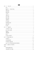
CPC-3813-MIL H7 D23 D22 D21 D20 H6 SW1 H13 H10 H3 H1 H12 H9 H2 H11 H8 H5 H4 J1 J2 第二章 安装说明 接口位置示意图 - 5 -
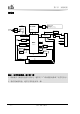
第二章 安装说明 架构图 g SATA4 DDR3 CH A DDR3 On Board Terminaltion SDRAM/SAMSUNG/ROHS (KW)K4B2G0846D-HCH9 DDR3 A I7-620UE FlashRom 8GX8bit JMF601 BGA1288 Hardware Monitor SATA1,2,3,4 FDI SATA3 COM3 SATA COM2 COM1 PCI PCI6150 J1 PS2 SCH3114 LPC Connector FlashRom 8GX8bit dummy DMIX4 8G SSD SATA4 DVI QM57 DVI PCIEX1 PCIEX1 USB3,4 SPI Flash1 USB 2.
第二章 安装说明 复位按钮 本板提供1个触发式复位按键SW1,实现Reset功能。 指示灯 灯 状态 描述 OFF 看门狗未操作 ON 看门狗正在操作当中 OFF 正常工作状态 ON 正处于热交换状态中 OFF 硬盘闲置 ON 硬盘运转 OFF 电源失败 ON 电源正常 看门狗 热交换 硬盘 电源 CPC-3813-MIL - 7 -
第二章 安装说明 Compact PCI接口 J1接头引脚信号定义 J1 管 脚 1 信号名称 A B C D E F +5V -12V TRST# +12V +5V GND 2 TCK +5V TMS# TDO TDI GND 3 INTA# IRQB# INTC# +5V INTD# GND 4 IPMB_PWR HEALTHY# V(I/O) INTP INTS GND 5 NC NC PCI_RST# GND GNT0# GND 6 REQ0# PCI_PRESENT# +3.3V CLK0 AD31 GND 7 AD30 AD29 AD28 GND AD27 GND 8 AD26 GND V(I/O) AD25 AD24 GND 9 C/BE3# GND AD23 GND AD22 GND 10 AD21 GND +3.
第二章 安装说明 J2接头引脚信号定义 J2 信号名称 管脚 A B C 22 GA4 GA3 GA2 GA1 GA0 GND 21 CLK6 GND USB1P/bi USB2P/bi PWR_USB1 GND 20 CLK5 GND USB1N/bi USB2N/bi PWR_USB2 GND 19 GND GND PWR_BTN#/in PWR_SLPS3#/out RIO_3.
第三章 第三章 BIOS 功能介绍 BIOS功能介绍 UEFI简介 UEFI(Unified Extensible Firmware Interface:标准的可扩展固件接口), 是新一代的计算机固件,用于取代传统的BIOS。UEFI固件存储在主板的闪存存储 器中,主要功能包括:初始化系统硬件,设置各系统部件的工作状态,调整各系 统部件的工作参数,诊断系统各部件的功能并报告故障,给上层软件系统提供硬 件操作控制接口,引导操作系统等。UEFI提供用户一个菜单式的人机接口,方便 用户配置各系统参数设置,控制电源管理模式,调整系统设备的资源分配等。 正确设置UEFI的各项参数,可使系统稳定可靠地工作,同时也能提升系统 的整体性能。不适当的甚至错误的UEFI参数设置,则会使系统工作性能大为降低, 使系统工作不稳定,甚至无法正常工作。 UEFI参数设置 每当系统接通电源,正常开机后,便可看见进入UEFI设置程序提示的信息。 此时(其它时间无效),按下提示信息所指定的按键(通常为键或键) 即可进入UEFI设置程序。 通过UEFI设置程序修改的所有设置值(除了日期、时间)都保存在系统的 闪存存储
第三章 BIOS 功能介绍 UEFI基本功能设置 当SETUP程序启动之后,您可以看到Aptio Setup Utility – Copyright (C) 2009 American Megatrends, Inc.主画面如下: Aptio Setup Utility – Copyright (C) 2009 American Megatrends, Inc. Main Advanced CPC-3813-MIL BIOS Name BIOS Version Build Date Chipset Boot Y9051000 A00 11/01/2010 Security Save & Exit Set the Date. Use‘Tab’ to switch between Date elements.
第三章 BIOS 功能介绍 Advanced Aptio Setup Utility – Copyright (C) 2009 American Megatrends, Inc. Main Advanced Chipset Boot Security Save & Exit WARNING: Setting wrong values in below sections →←:Select Screen ↑↓:Select Item may cause system to malfunction! Enter:Select +/-:Change Opt CPU Configuration F1:General Help SATA Configuration F2:Previous Values USB Configuration F3:Optimized Super IO Configuration Defaults H/W Monitor F4:Save ESC:Exit Version 2.00.1201.
第三章 BIOS 功能介绍 显示CPU的相关信息。注意,CPU的Type, Speed, Core, HT等跟平台所安装的CPU 有关,不同系列的CPU所显示的信息不同。 Hyper-Threading Hyper Threading Technology功能的控制开关。 Active Processor Cores 使能CPU的核的个数,只对多核CPU有效。 Hardware Prefetcher 打开或者关闭MLC Streamer Prefetcher。 Adjacent Cache Line Prefetch 打开或者关闭Prefetching of adjacent cache lines。 Intel Virtualization Technology Intel虚拟技术的开关。 SATA Configuration Aptio Setup Utility – Copyright (C) 2009 American Megatrends, Inc.
第三章 BIOS 功能介绍 SATA Port0~5动态侦测主板上有没有接SATA设备,如果对应的Port上有接设备, 则显示该SATA设备的型号。否则,显示Not Present。 Serial-ATA Controller 0 Serial-ATA Controller 0的开关,设置Serial-ATA Controller 0模式。 Serial-ATA Controller 1 Serial-ATA Controller 1的开关,设置Serial-ATA Controller 1的模式。 USB Configuration Aptio Setup Utility – Copyright (C) 2009 American Megatrends, Inc.
第三章 BIOS 功能介绍 Super IO Configuration Aptio Setup Utility – Copyright (C) 2009 American Megatrends, Inc. Advanced Super IO Configuration Floppy Disk Controller Configuration Serial Port 0 Configuration Serial Port 1 Configuration →←:Select Screen ↑↓:Select Item Enter:Select +/-:Change Opt F1:General Help F2:Previous Values F3:Optimized Defaults F4:Save ESC:Exit Version 2.00.1201. Copyright (C) 2009,American Megatrends, Inc.
第三章 BIOS 功能介绍 * Device Mode 此项用于配置软盘控制器工作模式。 Serial Port 1~2 Configuration Aptio Setup Utility – Copyright (C) 2009 American Megatrends, Inc. Advanced Serial Port 1~2 Configuration Serial Port Device Settings [Enabled] IO=3F8h; IRQ=4; Change Settings Device Mode [Auto] [Normal] →←:Select Screen ↑↓:Select Item Enter:Select +/-:Change Opt F1:General Help F2:Previous Values F3:Optimized Defaults F4:Save ESC:Exit Version 2.00.1201. Copyright (C) 2009,American Megatrends, Inc.
第三章 BIOS 功能介绍 H/W Monitor Aptio Setup Utility – Copyright (C) 2009 American Megatrends, Inc. Advanced PC Health Status CPU Temperature System Temperature : +38℃ : +36℃ Vcore V3.3 V5.0 V12.0 Vbat : : : : : +0.95 V +3.296 V +5.007 V +12.091 V +3.21 V →←:Select Screen ↑↓:Select Item Enter:Select +/-:Change Opt F1:General Help F2:Previous Values F3:Optimized Defaults F4:Save ESC:Exit Version 2.00.1201. Copyright (C) 2009,American Megatrends, Inc.
第三章 BIOS 功能介绍 Chipset Aptio Setup Utility – Copyright (C) 2009 American Megatrends, Inc. Main Advanced Chipset Boot Security Save & Exit WARNING: Setting wrong values in below sections →←:Select Screen may cause system to malfunction! ↑↓:Select Item Enter:Select South Bridge +/-:Change Opt F1:General Help F2:Previous Values F3:Optimized Defaults F4:Save ESC:Exit Version 2.00.1201. Copyright (C) 2009,American Megatrends, Inc.
第三章 BIOS 功能介绍 USB Configuration Aptio Setup Utility – Copyright (C) 2009 American Megatrends, Inc. Chipset USB Configuration USB Port 1 USB Port 2 [Enabled] [Enabled] →←:Select Screen ↑↓:Select Item Enter:Select +/-:Change Opt F1:General Help F2:Previous Values F3:Optimized Defaults F4:Save ESC:Exit Version 2.00.1201. Copyright (C) 2009,American Megatrends, Inc. * USB Port 0~3 USB Port 0~3 的开关。 Boot Aptio Setup Utility – Copyright (C) 2009 American Megatrends, Inc.
第三章 BIOS 功能介绍 Bootup Numlock State 小键盘数字键的开关。 Boot Option Priorities 此项用于配置系统引导的优先次序。其中,#1优先级最高,#n优先级最低。 Hard Drive BBS Priorities 此项用于配置传统设备在BBS中的优先次序。#1优先级最高,#n最低。 Security Aptio Setup Utility – Copyright (C) 2009 American Megatrends, Inc.
第三章 BIOS 功能介绍 注:如果只设置管理员密码,则只当进入Setup设置程序时需要输 入管理员密码; 如果只设置了用户密码,则开机启动时必须输入用户密码,如 果进入Setup设置程序,则具有管理员权限; 如果同时设置了管理员密码和用户密码,则开机启动时必须输 入管理员密码或者用户密码。如果使用管理员密码时,则在Setup 设置程序中具有管理员权限;如果使用用户密码,则在Setup设置 程序中只具有用户权限。 Save & Exit Aptio Setup Utility – Copyright (C) 2009 American Megatrends, Inc.
第三章 BIOS 功能介绍 Save Changes and Exit 此项用于保存修改并退出Setup设置程序。如果所作修改需要重启才能生 效,则会自动进行重启。 Discard Changes and Exit 此项用于放弃所作修改并退出Setup设置程序。 Save Changes and Reset 此项用于保存修改并重启。 Discard Changes and Reset 此项用于放弃所作修改并重启。 Save Changes 保存修改。 Discard Changes 放弃修改。 Restore Defaults 恢复默认值。 Save as User Defaults 保存用户默认值。 Restore User Defaults 恢复用户默认值。 Boot Override 此项中列出了所有的启动选项,用户可选择其中一项,并按下,即 可按该选项进行引导。 - 22 - CPC-3813-MIL
第三章 BIOS 功能介绍 x86 平台下UEFI所要管理的系统资源 这里的系统资源我们定义三种:I/O端口地址,IRQ中断号和DMA号。 DMA 级别 功能 DMA0 未分配 DMA1 未分配 DMA2 未分配 DMA3 未分配 DMA4 用于 DMAC 的级联 DMA5 未分配 DMA6 未分配 DMA7 未分配 APIC 高级可编程中断控制器。在现代P4以上级别的主板中,大都支持APIC,可 以提供多于16个中断源,如IRQ16—IRQ23,部分主板如支持PCI-X的主板可以有 多达28个中断源。但要启用该功能必须相应的操作系统支持。 IO端口地址 X86的I/O地址线只设计16条,从0~0FFFFh,I/O地址空间总共有64K,在传 统的ISA接口,只使用到前面的1024个(0000~03FFh),0400h以上的端口为PCI 接口与EISA接口所使用。每一外围设备都会占用一段I/O地址空间。下表给出了 X86平台大致上所要用到的I/O接口列表。 CPC-3813-MIL - 23 -
第三章 地 址 BIOS 功能介绍 设备描述 000h - 000Fh DMA 控制器#1 020h - 021h 可编程中断控制器#1 040h - 043h 系统计时器#1 061h – 061h 系统 Speaker 070h - 071h 系统 CMOS/实时时钟 081h - 083h DMA 控制器#2 087h – 087h DMA 控制器#3 089h – 08Bh DMA 控制器#4 08Fh – 08Fh DMA 控制器#5 0A0h – 0A1h 可编程中断控制器#2 0C0h – 0DFh DMA 控制器#6 0F0h – 0FFh 数据数值处理器 170h – 177h 次要 IDE 通道 1F0h – 1F7h 主要 IDE 通道 274h – 277h ISAPNP Read Data Port 279h – 279h ISAPNP Read Data Port 2F8h – 2FFh 通讯端口(COM2) 3B0h – 3BBh Intel(R) Graphic Media Accelerator H
第三章 BIOS 功能介绍 IRQ中断分配表 系统共0有15个中断源,有些已被系统设备独占。只有未被独占的中断才可 分配给其它设备使用。ISA设备要求独占使用中断;只有即插即用ISA设备才可由 UEFI或操作系统分配中断。而多个PCI设备可共享同一中断,并由UEFI或操作系 统分配。下表给出了X86平台部分设备的中断分配情况,但没有给出PCI设备所占 用的中断资源。 级别 功能 IRQ0 系统计时器 IRQ1 保留 IRQ2 保留 IRQ3 串口#2 IRQ4 串口#1 IRQ5 保留 IRQ6 Standard floppy disk controller IRQ7 保留 IRQ8 系统 CMOS/实时时钟 IRQ9 ACPI 兼容系统 IRQ10 保留 IRQ11 保留 IRQ12 保留 IRQ13 数据数值处理器 IRQ14 保留 IRQ15 保留 CPC-3813-MIL - 25 -
第四章 第四章 驱动程序安装说明 驱动程序安装说明 本产品的驱动程序可依据配套光盘内容安装,在此不做介绍。 - 26 - CPC-3813-MIL
附录 附录 Watchdog编程指引 本主板提供一个可按分或按秒计时的,最长达255级的可编程看门狗定时器 (以下简称WDT)。通过编程,WDT超时事件可用来将系统复位或者产生一个可屏蔽 中断。 本主板可使用的中断号为:3,4,5,7,9,10,11。以下用C语言形式提供 了WDT的编程范例,对WDT的编程需遵循以下步骤: 进入WDT编程模式 设置WDT工作方式,启动或关闭WDT。 (1) 进入WDT编程模式。 /* 描述:函数PreInitWDT用于初始化WDT相关的寄存器,请在设置并使用WDT 之前调用一次此函数。 输入:无 输出:无 注意:此函数会修改变量pm_base的值,并且pm_base会被设置WDT的函数 SetWDT引用。 */ #define INDEX_PORT 0x4E #define DATA_PORT 0x4F unsigned int tmp_reg; unsigned int pm_base; VOID PreInitWDT() { outportb(INDEX_PORT, 0x55); outportb(INDEX_PORT, 0x07); out
附录 outportb(INDEX_PORT, 0x30); outportb(DATA_PORT, 0x01); outportb(INDEX_PORT, 0x60); tmp_reg = inportb(DATA_PORT); pm_base = tmp_reg; outportb(INDEX_PORT, 0x61); tmp_reg = inportb(DATA_PORT); pm_base = pmbase<<8+tmp_reg; /*此处得到变量pm_base供后续程序 使用*/ } (2) 配置WDT工作方式,启动或关闭WDT。 /* 描述:函数SetWDT用于配置WDT需要的参数,启动或关闭WDT。 输入:Wmode: 0 - 配置WDT成复位工作方式 IRQ_NO - 配置WDT成中断工作方式,此处请用需要使 用的中断号替换掉常量IRQ_NO,文档前端已经列出可使 用中断号的范围。(注:中断模式的说明仅适用于ACPI 和APIC同时打开的OS。) Wtime: 0 1 Timeout: 0 配置WDT按分计时 - - 配置WDT按秒计时 停止WDT TIME_O
附录 outportb(pm_base+0x47, 0x0C); else { unsigned int irq; irq = Wmode; irq = irq<<4; outportb(pm_base+0x47, 0x80); outportb(pm_base+0x67, irq); } If (Wtime == 0) outportb(pm_base+0x65, 0x00); else outportb(pm_base+0x65, 0x80); outportb(pm_base+0x65, Timeout); } CPC-3813-MIL - 29 -
附录 常见故障分析与解决 序号 故障现象 故障分析解决 分析:可能是 CMOS 电池的问题。 1 BIOS 设置不能保 存 解决方法:用万用表测量 CMOS 电池,电压不足就 更换新电池,重新设置保存。 分析:可能是电源接触不良,从主板电源插座上拔 下电源,发现主板电源插针某根插针经多次用力插 2 时可开机时不可 压,已经倒向一边。 开机 解决方法:关机拔下电源插头,用镊子将弯曲的电 源插针弄直插上电源开关,重新启动,多次试验, 没有出现此类故障。 分析:U 盘是高速 USB2.0,接到电脑上有提示一个 当接上 U 盘时,系 3 统提示一个高速 高速设备接到一个低速接口上,说明主板的接口被 认为是一个 USB1.
附录 分析:可能是由于在安装光驱时不小心碰撞了硬盘 的数据线,从而使硬盘数据线接口接触不良导致 的,或者是硬盘和光驱上的主从跳线设置不正确。 5 更换光驱后系统 无法启动 解决方法:首先对硬盘数据线和硬盘及主板上的 IDE 接口进行检查,发现没有问题;然后检查主从 跳线的设置,发现硬盘和光驱连接在不同的数据线 上,而且硬盘和光驱的跳线都设置为主盘,从而导 致硬盘无法启动;将光驱的跳线设置为从盘,重新 安装好。 分析:确认 PCI 卡功能是否正常;将 PCI 卡重插或 插入其他 PCI 插槽,看能否正常;了解使用的电源 类型(是 AT 还是 ATX);了解客户的 PCI 卡的电压 需求。 6 进入系统后无法 检测到 PCI 卡 解决方法:如 PCI 卡功能问题,更换 PCI 卡解决; 重插或插入其他 PCI 插槽即可正常,则为 PCI 卡与 插槽接触问题。如果使用的是 AT 电源,但 PCI 卡 需要 3.3V 电压,因为 AT 电源不提供 3.3V 电压, 电源需更换为 ATX 电源方可使用 PCI 卡。(建议: 在选购电源时,先了解所使用的 PCI 卡是否需要 3.
Copyright Notice Information offered in this manual is believed to be correct at the time of printing, and is subject to change without prior notice in order to improve reliability, design and function and does not represent a commitment on the part of the manufacturer. In no event will the manufacturer be liable for direct, indirect, special, incidental, or consequential damages arising out of improper installation and/or use, or inability to use the product or documentation.
Safety Instructions 1. Please read this manual carefully before using the product; 2. Leave the board or card in the antistatic bag until you are ready to use it; 3. Touch a grounded metal object (e.g. for 10 seconds) before removing the board or card from the anti-static bag; 4. Before installing or removing a board, wear the ESD gloves or ESD wrist strap; handle the board by its edges only; 5.
Contents Chapter 1 Product Introduction.....................................................................................1 Overview ......................................................................................................................1 Mechanical Dimensions, Weight and Environment ......................................................2 Typical Consumption....................................................................................................2 Microprocessor ...................
Chapter 1 Product Introduction Chapter 1 Product Introduction Overview The board adopts Intel® Calpella + ECC platform with i7-620UE 1.06GHz high-performance and low power consumption processor and QM57 Express Chipset. The Core™i7-620UE processor adopts 32nm craft and dual-core four-thread processing mechanism; the performance can be improved via Intel® Turbo Boost technology. The i7 processor integrates DDR3 800/1066MHz memory controller and video card controller.
Chapter 1 Product Introduction The board is a high-end 3U CompactPCI motherboard, which can meet customers’ different requirements for connectors. The product is mainly applied in the high-end CPCI products in the fields of information communication, network storage, network audio processing, network graphics processing, industrial control, military and aviation, etc. Mechanical Dimensions, Weight and Environment Dimensions: 169.3mm (L) x 100mm (W) x 15.5mm (H); Net Weight: 0.
Chapter 1 Product Introduction Microprocessor Provides Intel® Core™ i7-620UE CPU, which adopts BGA1288 package, DMI: 2.5GT/S, 32nm craft, dual-core four-thread mechanism, main frequency: 1.06GHZ and rated power consumption: 18W. Chipset Mobile Intel® QM57 Express Chipset System Memory DDR3 ECC SDRAM 800/1066MHz memory IC on-board, supporting Un-buffered ECC and single-channel function. The maximum memory capacity supported by a single memory bank is up to 2GB.
Chapter 1 Product Introduction Expansion Bus Provides seven 32-bit CPCI slots, complying with CompactPCI standard. Watchdog Function 255 levels, programmable by minute or second; Supports watchdog timeout interrupt or reset system. Operating System Supported OSs: Windows XP, Vxworks and linux.
Chapter 2 Installation Chapter 2 Installation Product Outline 100 H4 H5 J1 J2 19.9 H8 H11 13.5 H2 15.5 H1 H9 160 H12 32.5 H7 D23 D21 D22 D20 H6 SW1 H10 H13 H3 48 20.8 2.5 15.5 10 Unit: mm Warning! Please adopt appropriate screws and proper installation methods (including board allocation, CPU and heat sink installation, etc); otherwise, the board may be damaged. It is recommended to use M3x6 GB9074.4-88 screws at H1 ~ H3, M2.5x4 GB/T 818-2000 screws at H4 ~ H7 and M2.
Chapter 2 Installation -6- H7 D23 D21 D22 D20 H6 SW1 H10 H13 H3 H1 H9 H12 H2 H8 H11 H4 H5 J1 J2 Locations of Connectors CPC-3813-MIL
Chapter 2 Installation Structure SATA4 DDR3 CH A DDR3 On Board Terminaltion SDRAM/SAMSUNG/ROHS (KW)K4B2G0846D-HCH9 DDR3 A I7-620UE FlashRom 8GX8bit JMF601 BGA1288 Hardware Monitor SATA1,2,3,4 FDI SATA3 COM3 SATA LPC COM2 COM1 PCI PCI6150 J1 PS2 SCH3114 Connector FlashRom 8GX8bit dummy DMIX4 8G SSD SATA4 DVI QM57 DVI PCIEX1 PCIEX1 USB3,4 SPI Flash1 USB 2.
Chapter 2 Installation Reset Button The board provides one trigger mode reset button, SW1, to realize Reset function.
Chapter 2 Installation CompactPCI Connector The pin definitions for J1 J1 Signal Name Pin A B C D E F 1 +5V -12V TRST# +12V +5V GND 2 TCK +5V TMS# TDO TDI GND 3 INTA# IRQB# INTC# +5V INTD# GND 4 IPMB_PWR HEALTHY# V(I/O) INTP INTS GND 5 NC NC PCI_RST# GND GNT0# GND 6 REQ0# PCI_PRESENT# +3.3V CLK0 AD31 GND 7 AD30 AD29 AD28 GND AD27 GND 8 AD26 GND V(I/O) AD25 AD24 GND 9 C/BE3# GND AD23 GND AD22 GND 10 AD21 GND +3.
Chapter 2 Installation The pin definitions for J2 J2 Signal Name Pin A B C D E F 22 GA4 GA3 GA2 GA1 GA0 GND 21 CLK6 GND USB1P/bi USB2P/bi PWR_USB1 GND 20 CLK5 GND USB1N/bi USB2N/bi PWR_USB2 GND 19 GND GND PWR_BTN#/in RIO_3.
Chapter 3 BIOS Setup Chapter 3 BIOS Setup UEFI Overview UEFI (Unified Extensible Firmware Interface) is the latest computer firmware to replace traditional BIOS. UEFI is solidified in the flash memory on the CPU board.
Chapter 3 BIOS Setup Basic Function Setting for UEFI After starting SETUP program, the main interface of Aptio Setup Utility - Copyright (C) 2009 American Megatrends, Inc. will appear: Aptio Setup Utility – Copyright (C) 2009 American Megatrends, Inc.
Chapter 3 BIOS Setup Advanced Aptio Setup Utility – Copyright (C) 2009 American Megatrends, Inc. Main Advanced Chipset Boot Security Save & Exit WARNING: Setting wrong values in below sections may cause system to malfunction! CPU Configuration SATA Configuration USB Configuration Super IO Configuration H/W Monitor →←: Select Screen ↑↓: Select Item Enter: Select +/-: Change Opt F1: General Help F2: Previous Values F3: Optimized Defaults F4: Save ESC: Exit Version 2.00.1201.
Chapter 3 BIOS Setup Display the relevant information of CPU. Note: the Type, Speed, Core and HT of the CPU are related to the CPU installed in the platform; different series CPUs will display different information. Hyper-Threading Control switch for the Hyper Threading Technology function. Active Processor Cores Active CPU core number, only available for multi-core CPU. Intel Virtualization Technology Switch of the Intel virtualization technology.
Chapter 3 BIOS Setup USB Configuration Aptio Setup Utility – Copyright (C) 2009 American Megatrends, Inc. Advanced USB Configuration USB Devices: 1 Keyboard, 1 Mouse, 2 Hubs Legacy USB Support [Enabled] →←: Select Screen ↑↓: Select Item Enter: Select +/-: Change Opt F1: General Help F2: Previous Values F3: Optimized Defaults F4: Save ESC: Exit Version 2.00.1201. Copyright (C) 2009,American Megatrends, Inc.
Chapter 3 BIOS Setup Floppy Disk Controller Configuration Aptio Setup Utility – Copyright (C) 2009 American Megatrends, Inc. Advanced Floppy Disk Controller Configuration Floppy Disk Controller Device Settings [Enabled] Reset Required Change Settings Device Mode [Auto] [Read Write] →←: Select Screen ↑↓: Select Item Enter: Select +/-: Change Opt F1: General Help F2: Previous Values F3: Optimized Defaults F4: Save ESC: Exit Version 2.00.1201. Copyright (C) 2009,American Megatrends, Inc.
Chapter 3 BIOS Setup Serial Port 1 ~ 2 Configuration Aptio Setup Utility – Copyright (C) 2009 American Megatrends, Inc. Advanced →←: Select Screen Serial Port 1 ~ 2 Configuration ↑↓: Select Item Serial Port [Enabled] Enter: Select Device Settings IO=3F8h; IRQ=4; +/-: Change Opt F1: General Help Change Settings Device Mode [Auto] [Normal] F2: Previous Values F3: Optimized Defaults F4: Save ESC: Exit Version 2.00.1201. Copyright (C) 2009,American Megatrends, Inc.
Chapter 3 BIOS Setup H/W Monitor Aptio Setup Utility – Copyright (C) 2009 American Megatrends, Inc. Advanced PC Health Status CPU Temperature System Temperature Vcore V3.3 V5.0 V12.0 Vbat : +38 C : +36 C : +0.95 V : +3.296 V : +5.007 V : +12.091 V : +3.21 V →←: Select Screen ↑↓: Select Item Enter: Select +/-: Change Opt F1: General Help F2: Previous Values F3: Optimized Defaults F4: Save ESC: Exit Version 2.00.1201. Copyright (C) 2009,American Megatrends, Inc.
Chapter 3 BIOS Setup Chipset Aptio Setup Utility – Copyright (C) 2009 American Megatrends, Inc. Main Advanced Chipset Boot Security Save & Exit WARNING: Setting wrong values in below sections may cause system to malfunction! South Bridge →←: Select Screen ↑↓: Select Item Enter: Select +/-: Change Opt F1: General Help F2: Previous Values F3: Optimized Defaults F4: Save ESC: Exit Version 2.00.1201. Copyright (C) 2009,American Megatrends, Inc.
Chapter 3 BIOS Setup USB Configuration Aptio Setup Utility – Copyright (C) 2009 American Megatrends, Inc. Chipset USB Configuration USB Port 1 USB Port 2 →←: Select Screen ↑↓: Select Item Enter: Select +/-: Change Opt F1: General Help F2: Previous Values F3: Optimized Defaults F4: Save ESC: Exit [Enabled] [Enabled] Version 2.00.1201. Copyright (C) 2009,American Megatrends, Inc. * USB Port 0 ~ 3 Switch for USB Port 0 ~ 3. Boot Aptio Setup Utility – Copyright (C) 2009 American Megatrends, Inc.
Chapter 3 BIOS Setup Switch for the Numlock. Boot Option Priorities This option is used to configure the system booting priorities. #1 represents the highest priorities while #n represents the lowest priorities. Hard Drive BBS Priorities This option is used to configure the priorities of the legacy devices in BBS. #1 represents the highest priorities while #n represents the lowest priorities. Security Aptio Setup Utility – Copyright (C) 2009 American Megatrends, Inc.
Chapter 3 BIOS Setup Note: If ONLY the Administrator's password is set, then this is only asked for when entering Setup; If ONLY the User's password is set, then this must be entered to boot the computer. When entering Setup, the User will have Administrator privileges; When both Administrator's password and User's password are set, Administrator's password or User's password is required when booting.
Chapter 3 BIOS Setup Save Changes and Exit This option is used to save changes and exit Setup program. If the changes are effective after rebooting, then it will reboot automatically. Discard Changes and Exit This option is used to discard changes and exit Setup program. Save Changes and Reset The option is used to save changes and reset. Discard Changes and Reset The option is used to discard changes and reset. Save Changes Save changes. Discard Changes Discard changes.
Chapter 3 BIOS Setup System Resource Managed by UEFI under x86 Platform We define three kinds of system resources here: I/O port address, IRQ interrupt number and DMA number. DMA Level Function DMA0 Unassigned DMA1 Unassigned DMA2 Unassigned DMA3 Unassigned DMA4 Used for DMAC cascade DMA5 Unassigned DMA6 Unassigned DMA7 Unassigned APIC Advanced programmable interrupt controller.
Chapter 3 BIOS Setup Address Device Description 000h - 000Fh DMA Controller #1 020h - 021h Programmable Interrupt Controller #1 040h - 043h System Timer#1 061h – 061h System Speaker 070h - 071h System CMOS/Real Time Clock 081h - 083h DMA Controller #2 087h – 087h DMA Controller #3 089h – 08Bh DMA Controller #4 08Fh – 08Fh DMA Controller #5 0A0h – 0A1h Programmable Interrupt Controller #2 0C0h – 0DFh DMA Controller #6 0F0h – 0FFh Numeric data processor 170h – 177h Secondary IDE Cha
Chapter 3 BIOS Setup IRQ Assignment Table There are 15 interrupt sources of the system. Some are occupied by the system devices. Only the ones that are not occupied can be distributed. The ISA devices claim to engross the interrupt. Only the plug and play ISA devices can be distributed by the BIOS or the OS. And several PCI devices share one interrupt through the distribution of BIOS or OS.
Chapter 4 Install the Drivers Chapter 4 Install the Drivers Regarding the driver program of this product, please refer to the enclosed CD.
Appendix Appendix Watchdog Programming Guide The board provides a programmable watchdog timer (WDT) up to 255 levels and timed by minute or second. Watchdog timeout event can be programmed to reset system or generate maskable interrupts. The available IRQ numbers for this board are: 3, 4, 5, 7, 9, 10 and 11. The following describes WDT program in C language. The steps to program WDT are listed as follows: Enter WDT programming mode; Set WDT operating mode, enable WDT/disable WDT.
Appendix outportb(DATA_PORT, 0x0A); outportb(INDEX_PORT, 0x30); outportb(DATA_PORT, 0x01); outportb(INDEX_PORT, 0x60); tmp_reg = inportb(DATA_PORT); pm_base = tmp_reg; outportb(INDEX_PORT, 0x61); tmp_reg = inportb(DATA_PORT); pm_base = pmbase<<8+tmp_reg; /*Get the variable pm_base for later use*/ } (2) Configure the WDT operating mode to enable or disable WDT /* Description: the function, SetWDT, is used to configure the parameter required when configuring WDT to enable or disable WDT.
Appendix { unsigned int irq; If (Wmode == 0) outportb(pm_base+0x47, 0x0C); else { unsigned int irq; irq = Wmode; irq = irq<<4; outportb(pm_base+0x47, 0x80); outportb(pm_base+0x67, irq); } If (Wtime == 0) outportb(pm_base+0x65, 0x00); else outportb(pm_base+0x65, 0x80); outportb(pm_base+0x65, Timeout); } - 30 - CPC-3813-MIL
Appendix Troubleshooting and Solutions NO. Phenomenon 1 BIOS setting cannot be saved 2 The computer can only be powered-on occasionally 3 When connecting with a USB flash drive, the system prompts that a high-speed device has been connected with a low-speed connector. Troubleshooting and Solution Analysis: it could be the problem of the CMOS battery.
Appendix 5 The system cannot be booted after replacing a CD-ROM. 6 No PCI card can be detected after entering the system. 7 No peripheral devices can be detected. - 32 - Analysis: the data cable of the hard disk may get knocked when installing the CD-ROM, which leads to poor connection of the hard disk data cable, or the master and slave jumpers on hard disk and CD-ROM are wrongly set.