BIPV10-IA Setup Manual FCC Information and Copyright This equipment has been tested and found to comply with the limits of a Class B digital device, pursuant to Part 15 of the FCC Rules. These limits are designed to provide reasonable protection against harmful interference in a residential installation. This equipment generates, uses, and can radiate radio frequency energy and, if not installed and used in accordance with the instructions, may cause harmful interference to radio communications.
Table of Contents Chapter 1: Introduction ........................................ 3 1.1 1.2 1.3 1.4 1.5 Before You Start ................................................................................ 3 Package Checklist ............................................................................. 3 Mainboard Specification................................................................... 4 Rear Panel..........................................................................................
BIPV10-IA CHAPTER 1: INTRODUCTION 1.1 BEFORE YOU START Thank you for choosing our product. Before you start installing the mainboard, please make sure you follow the instructions below: Prepare a dry and stable working environment with sufficient lighting. Always disconnect the system from power outlet before operation. Before you take the mainboard out from anti-static bag, ground yourself properly by touching any safely grounded appliance, or use grounded wrist strap to remove the static charge.
Mini-ITX Mainboard Manual 1.3 MAINBOARD SPECIFICATION Specification Intel CPU On-board CPU Optional for: Intel Atom D525 @1.8GHz dual core D425 @1.
BIPV10-IA Specification CPU Fan Header x1 System Fan Header x1 Clear CMOS Header x1 AT/ATX Power Switch Header x1 USB 2.
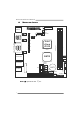
Mini-ITX Mainboard Manual 1.5 MAINBOARD LAYOUT JK B MS 1 JAT X PW R1 JLV 2 LVDS -OUT1 JLV 1 JP 2 JCFA N1 JCOM5 JBL2 JP 5 Intel Atom D525 JP 4 JCOM1 JP 3 CPU1 B A JP 6 DDR 3_A 2 JP 1 JBL1 JC1 DDR 3_A 1 JV GA 1 JCOM2 JCOM6 JCMOS1 NM10 JRJ45USB 1 JAUDIO1 BAT1 P E1 JDIO1 JPRNT1 P CI1 Note: ■ represents the 1st pin.
BIPV10-IA CHAPTER 2: INSTALLATION 2.1 CPU The mainboard includes an embedded Intel Atom D525 processor, and a heatsink has been installed to provide sufficient cooling. 2.2 FAN HEADER The fan header supports cooling-fans built in the system. The fan cable and connector may be different due to the fan manufacturer.
Mini-ITX Mainboard Manual 2.3 SYSTEM MEMORY DD R3_A 1 DD R3_A 2 DDR3_A1/DDR3_A2: Memory Module (LONG-DIMM) 2 Align a DIMM on the slot such that the notch on the DIMM matches the break on the Slot. 3 Insert the DIMM firmly into the slot until the retaining chip snap back in place and the DIMM is properly seated. Memory Capacity DIMM Socket Location DDR3 Module DDR3_A1 512MB/1GB/2GB Total Memory Size Max is 4GB.
BIPV10-IA 2.4 POWER SUPPLY JATXPWR1: ATX Power Source Connector (20-pin) This connector allows user to connect 20-pin power connector on the power supply. Pin 1 2 3 4 5 6 7 8 9 10 Assignment +3.3V +3.3V GND +5V GND +5V GND Power Good +5V Standby +12V Pin 11 12 13 14 15 16 17 18 19 20 20 11 10 1 Assignment +3.
Mini-ITX Mainboard Manual 2.5 ONBOARD SLOT/CONNECTOR/HEADER/JUMPER PCI1: Peripheral Component Interconnect Slot This mainboard is equipped with 1 standard PCI slot. PCI stands for Peripheral Component Interconnect, and it is a bus standard for expansion cards. This PCI slot is designated as 32 bits. PCI1 PE1: Mini PCI-E Slot This mainboard is equipped with 1 Mini PCI-E Slot.
BIPV10-IA SATA1/SATA2: Serial ATA Connectors These next generation connectors support the thin Serial ATA cable for primary internal storage devices. The current Serial ATA interface allows up to 3.0 Gbit/s data transfer rate. Pin Assignment 1 GND 2 TX+ 3 TX- 4 GND 1 5 RX- 4 6 RX+ 7 7 GND SA TA2 SATA1 USB1/USB2: USB 2.0 Headers The mainboard provides 2 front USB pin header, allowing up to 3 additional USB 2.0 ports up to maximum throughput of 480 Mbps.
Mini-ITX Mainboard Manual JPANEL1: Front Panel Header This 10-pin header includes Power-on, Reset, HDD LED, and Power LED connection. It allows user to connect the system case’s front panel switch functions.
BIPV10-IA JCOM1 / JCOM3 / JCOM4: Serial port Connectors The motherboard has 3 Serial Port Connectors for connecting RS-232 Port.
Mini-ITX Mainboard Manual JP2: Voltage Switch Header for JCOM2 This header is for controlling the Pin10 of JCOM2 to switch 5V or 12V. 3 1 3 1 Pin 1-2 Close: Pin10=5V 3 1 Pin 2-3 Close: Pin10=12V (Default) JP1: Voltage Switch Header for JCOM1 This header is for controlling the Pin9 of JCOM1 to switch Ring or 5V. 3 1 3 1 Pin 1-2 Close: Pin9=5V 3 1 Pin 2-3 Close: Pin9=Ring (Default) JP5: Voltage Switch Header for JCOM5 This header is for controlling the Pin10 of JCOM5 to switch 5V or 12V.
BIPV10-IA JP4: Voltage Switch Header for JCOM4 This header is for controlling the Pin9 of JCOM4 to switch Ring or 5V. 3 3 1 1 Pin 1-2 Close: Pin9=5V 3 1 Pin 2-3 Close: Pin9=Ring (Default) JP3: Voltage Switch Header for JCOM3 This header is for controlling the Pin9 of JCOM3 to switch Ring or 5V. 3 1 3 1 Pin 1-2 Close: Pin9=5V 3 1 Pin 2-3 Close: Pin9=Ring (Default) JP6: Voltage Switch Header for JCOM6 This header is for controlling the Pin10 of JCOM6 to switch 5V or 12V.
Mini-ITX Mainboard Manual JCMOS1: Clear CMOS Header * Placing the jumper on pin2-3 allows user to restore the BIOS safe setting and the CMOS data. Please carefully follow the procedures to avoid damaging the mainboard. 1 3 Pin 1-2 Close: (Default) Normal Operation. 1 3 3 1 Pin 2-3 Close: Clear CMOS data. ※ Clear CMOS Procedures: 1. Remove AC power line. 2. Set the jumper to “Pin 2-3 close”. 3. Wait for five seconds. 4. Set the jumper to “Pin 1-2 close”. 5. Power on the AC. 6.
BIPV10-IA LVDS-CONN1: LVDS Connector This connector is for devices requiring display interface such as LVDS. This connector supports 18/24 bit single-channel panels up to 1366 x 768 It is strongly recommended to use the matching JOY DAY INDUSTRIAL A1252WV-SF-2X20PD01 connector. Pin Assignment 1 39 2 40 Pin Assignment 1 NC 2 PVDD (+3.3V or +5V or +12V) 3 NC 4 PVDD (+3.
Mini-ITX Mainboard Manual JLV2: LCD Power Select Header * This header allows you to select LCD Power. 2 2 6 1 5 1 Pin 1-2 Close: PVDD=3.3V (Default) 4 3 Pin 2-3 Close: PVDD=5V 6 5 Pin 2-3 Close: PVDD=12V JLV1: LCD Backlight Inverter Power Select Header * This header is for selecting LCD Backlight Inverter Power.
BIPV10-IA JBL2: LCD Backlight Brightness Adjust Header * This header is for adjusting LCD backlight brightness. 2 1 4 3 2 1 4 3 Short Pin 1-2: Increase Brightness 2 1 4 3 Short Pin 3-4: Decrease Brightness JC1: LCD Backlight Inverter Connector This connector is for connecting to LCD for providing backlight control function. It is strongly recommended to use the matching JOY DAY INDUSTRIAL - A1250WV-S-8P connector.
Mini-ITX Mainboard Manual JPRNT1: Printer Port Connector This header allows you to connect printer port on the PC. 26 2 1 Pin 1 2 3 4 5 6 7 8 9 10 11 12 13 Assignment -Strobe -ALF Data 0 -Error Data 1 -Init Data 2 -Scltin Data 3 Ground Data 4 Ground Data 5 Pin 14 15 16 17 18 19 20 21 22 23 24 25 26 25 Assignment Ground Data 6 Ground Data 7 Ground -ACK Ground Busy Ground PE Ground SCLT Key *How to Setup Jumpers The illustration shows how to set up jumpers.
BIPV10-IA CHAPTER 3: BIOS SETUP Introduction The purpose of this chapter is to describe the settings in the AMI BIOS Setup program on this motherboard. The Setup program allows users to modify the basic system configuration and save these settings to CMOS RAM. The power of CMOS RAM is supplied by a battery so that it retains the Setup information when the power is turned off. Basic Input-Output System (BIOS) determines what a computer can do without accessing programs from a disk.
Mini-ITX Mainboard Manual PCI Bus Support This AMI BIOS also supports Version 2.3 of the Intel PCI (Peripheral Component Interconnect) local bus specification. DRAM Support DDR2 SDRAM (Double Data Rate II Synchronous DRAM) is supported. Supported CPUs This AMI BIOS supports the Intel CPU. Using Setup When starting up the computer, press during the Power-On Self-Test (POST) to enter the BIOS setup utility.
BIPV10-IA 3.1 MAIN MENU Once you enter AMI BIOS Setup Utility, the Main Menu will appear on the screen providing an overview of the basic system information. Main Advanced PCIPnP BIOS SETUP UTILITY Boot Chipset Use [ENTER], [TAB] or [SHIFT-TAB] to select a field. System Overview AMI BIOS Version :01.01.01 Build Date:01/01/10 System Memory Size : System Time System Date > IDE Configuration Exit Use [+] or [-] to configure system Time.
Mini-ITX Mainboard Manual IDE Configuration The BIOS will automatically detect the presence of IDE/SATA devices. There is a sub-menu for each IDE/SATA device. Select a device and press to enter the sub-menu of detailed options.
BIPV10-IA The BIOS detects the information and values of respective devices, and these information and values are shown below to the name of the sub-menu. Type Select the type of the SATA drive. Options: Auto (Default) / CD/DVD / ARMD / Not Installed LBA/Large Mode Enable or disable the LBA mode. Options: Auto (Default) / Disabled Block (Multi-Sector Transfer) Enable or disable multi-sector transfer. Options: Auto (Default) / Disabled PIO Mode Select the PIO mode.
Mini-ITX Mainboard Manual 3.2 ADVANCED MENU The Advanced Menu allows you to configure the settings of CPU, Super I/O, Power Management, and other system devices. Notice z Beware of that setting inappropriate values in items of this menu may cause system to malfunction. Main Advanced PCIPnP BIOS SETUP UTILITY Boot Chipset Advanced Settings Exit Configure CPU. WARNING: Setting wrong values in below sections may cause system to malfunction.
BIPV10-IA Max CPUID Value Limit When the computer is booted up, the operating system executes the CPUID instruction to identify the processor and its capabilities. Before it can do so, it must first query the processor to find out the highest input value CPUID recognizes. This determines the kind of basic information CPUID can provide the operating system.
Mini-ITX Mainboard Manual Serial Port2 Address Select an address and corresponding interrupt for Serial Port 2. Options: 2F8/IRQ3 (Default) / 3E8/IRQ4 / 2E8/IRQ3 / Disabled Parallel Port Address This item allows you to determine access onboard parallel port controller with which I/O Address. Options: 378 (Default) / 278 / 3BC / Disabled Parallel Port Mode This item allows you to determine how the parallel port should function. Options: Normal (Default) Using Parallel port as Standard Printer Port.
BIPV10-IA Serial Port3 Address This item allows you to select the address of Serial Port3. Options: 3E8 (Default) / 2E8 / 2F0 / 2E0 Serial Port3 IRQ This item allows you to select IRQ of Serial Port3. Options: IRQ5 (Default) / IRQ3 / IRQ4 / IRQ7 / IRQ9 / IRQ10 / IRQ11 / IRQ12 Serial Port4 Address This item allows you to select the address of Serial Port4. Options: 2E8 (Default) / 3E8 / 2F0 / 2E0 Serial Port4 IRQ This item allows you to select IRQ of Serial Port4.
Mini-ITX Mainboard Manual Watch Dog Degree This item allows you to determine the functional degree of Watch Dog. Options: Second (Default) / Minute Watch Dog Timer Options: 0 for disabled (Default) / Min=1, Max=65536 Hardware Health Configuration This item shows the system temperature, fan speed, and voltage information. Advanced BIOS SETUP UTILITY Hardware Health Configuration H/W Health Function Shutdown Temperature [Enabled] [Disabled] Enables Hardware Health Monitoring Device.
BIPV10-IA Smart Fan Configuration Advanced BIOS SETUP UTILITY Smart Fan Configuration JSFAN1 Smart Fan Smart Fan Calibration Control Mode o Fan Ctrl OFF( C) o Fan Ctrl On( C) Fan Ctrl Start value Fan Ctrl Sensitive [Disabled] When you choice [Auto] ,[3Pin] or [4Pin], please run the calibration to define the Fan parameters for Smart Fan control +F1 F10 ESC Select Screen Select Item Change Option General Help Save and Exit Exit vxx.xx (C)Copyright 1985-200x, American Megatrends, Inc.
Mini-ITX Mainboard Manual Fan Ctrl Start Value When CPU temperature arrives to the set value, the CPU/System fan will work under Smart Fan Function mode. Options: 0~127 (With the interval of 1) Fan Ctrl Sensitive Increasing the value of slope PWM will raise the speed of CPU fan.
BIPV10-IA Advanced ACPI Configuration Advanced BIOS SETUP UTILITY Advanced ACPI Configuration ACPI Version Features ACPI APIC support AMI OEMB table Headless mode [ACPI v1.0] [Enabled] [Enabled] [Disabled] Enable RSDP pointers to 64-bit Fixed System Description Tables. ACPI version has some +F1 F10 ESC Select Screen Select Item Change Option General Help Save and Exit Exit vxx.xx (C)Copyright 1985-200x, American Megatrends, Inc.
Mini-ITX Mainboard Manual Chipset ACPI Configuration Advanced BIOS SETUP UTILITY South Bridge ACPI Configuration Energy Lake Feature APIC ACPI SCI IRQ High Performance Event Timer HPET Memory Address [Disabled] [Disabled] [Disabled] [FED00000h] +F1 F10 ESC Select Screen Select Item Change Option General Help Save and Exit Exit vxx.xx (C)Copyright 1985-200x, American Megatrends, Inc. Energy Lake Feature This item allows you to enable or disable the Energy Lake technology feature.
BIPV10-IA RTC Alarm Time You can choose the system boot up time, input hour, minute and second to specify. Resume On PME# This item allows you to disable or enable PME to generate a wake event. Options: Disabled (Default) / Enabled Restore on AC Power Loss by IO This setting specifies how your system should behave after a power fail or interrupts occurs. By choosing Disabled will leave the computer in the power off state.
Mini-ITX Mainboard Manual USB 2.0 Controller Mode This item allows you to select the operation mode of the USB 2.0 controller. Options: HiSpeed (Default) USB 2.0-480Mbps FullSpeed USB 1.1-12Mbps BIOS EHCI Hand-Off This item allows you to enable support for operating systems without an EHCI hand-off feature.
BIPV10-IA 3.3 PCI/PNP MENU This section describes configuring the PCI bus system. PCI, or Personal Computer Interconnect, is a system which allows I/O devices to operate at speeds nearing the speed of the CPU itself uses when communicating with its own special components. Notice z Beware of that setting inappropriate values in items of this menu may cause system to malfunction.
Mini-ITX Mainboard Manual Allocate IRQ to PCI VGA This item allows BIOS to choose a IRQ to assign for the PCI VGA card. Options: Yes (Default) / No Palette Snooping Some old graphic controllers need to “snoop” on the VGA palette and then map it to their display as a way to provide boot information and VGA compatibility. This item allows such snooping to take place.
BIPV10-IA PCI Resource PCIPnP BIOS SETUP UTILITY PCI Resource IRQ3 IRQ4 IRQ5 IRQ7 IRQ9 IRQ10 IRQ11 IRQ14 IRQ15 DMA DMA DMA DMA DMA DMA [Available] [Available] [Available] [Available] [Available] [Available] [Available] [Available] [Available] Channel Channel Channel Channel Channel Channel 0 1 3 5 6 7 Reserved Memory Size [Available] [Available] [Available] [Available] [Available] [Available] Available: Specified IRQ is available to be used by PCI/PnP devices.
Mini-ITX Mainboard Manual 3.4 BOOT MENU This menu allows you to setup the system boot options. Main Advanced PCIPnP BIOS SETUP UTILITY Boot Chipset Specifies the Boot Device Priority sequence.
BIPV10-IA Quick Boot Enabling this option will cause an abridged version of the Power On Self-Test (POST) to execute after you power up the computer. Options: Enabled (Default) / Disabled Full Screen LOGO Disaply This item allows you to enable/disable Full Screen LOGO Show function. Options: Disabled (Default) / Enabled AddOn ROM Display Mode This item sets the display mode for option ROM.
Mini-ITX Mainboard Manual 3.5 CHIPSET MENU This submenu allows you to configure the specific features of the chipset installed on your system. This chipset manage bus speeds and access to system memory resources, such as DRAM. It also coordinates communications with the PCI bus. Notice z Beware of that setting inappropriate values in items of this menu may cause system to malfunction.
DRAM Frequency BIPV10-IA This item allows you to set the frequency of DRAM. Options: Auto (Default) / 800MHz Configure DRAM timing by SPD This item allows you .
Mini-ITX Mainboard Manual Video Function Configuration BIOS SETUP UTILITY Chipset Video Function Configuration Options DVMT Mode Select DVMT/FIXED Memory [DVMT Mode] [256MB] Boot Display Device LVDS SUPPORT Local Flat Panel Scaling Flat Panel Type [D-SUB + LVDS] [Enabled] [Auto] [1024 X 768] Fixed Mode DVMT Mode +F1 F10 ESC Select Screen Select Item Change Option General Help Save and Exit Exit vxx.xx (C)Copyright 1985-200x, American Megatrends, Inc.
BIPV10-IA Flat Panel Type This item allows you to select flat panel type. Options: 1024x768 (Default) / 640x480 / 800x600 / 1280x1024 / 1280x7684 / 1366x768 / 1400x1050 / 1280x768 / 1680x1050 / 1920x1200 / 1280x800 / 2048x1536 South Bridge Configuration BIOS SETUP UTILITY Chipset South Bridge Chipset Configuration USB Functions USB 2.
Mini-ITX Mainboard Manual SMBUS Controller This BIOS feature controls the I/O buffers for the SMBus. Options: Enabled (Default) / Disabled Onboard LAN 1/2 This item allows you to enable or disable the Onboard LAN. Options: Enabled (Default) / Disabled Onboard LAN ROM 1/2 This item allows you to select the Onboard LAN Boot ROM. Options: Disabled (Default) / Enabled PCIE High Priority Port Options: Disabled (Default) / Port 0 ~ Port 3 SLP_S4# Min.
BIPV10-IA Relaxed Ordering The item enables/disables PCI Express Device Relaxed Ordering. Options: Auto (Default) / Disabled / Enabled Maximum Payload Size The item sets Maximum Payload of PCI Express Device or allows System BIOS to select the value. Options: Auto (Default) / 128 Byte / 256 Byte / 512 Byte / 1024 Byte / 2048 Byte / 4096 Byte Extended Tag Field If this item is enabled, the system allows Device to use 8-bit TAG field as a requester.
Mini-ITX Mainboard Manual 3.6 EXIT MENU This menu allows you to load the optimal default settings, and save or discard the changes to the BIOS items. Main Advanced PCIPnP BIOS SETUP UTILITY Boot Chipset Exit Options Save Changes and Exit Discard Changes and Exit Discard Changes Load Optimal Defaults Exit Exit system setup after saving the changes. F10 key can be used for this operation.
BIPV10-IA Security This sub-menu allows you to provide/revise supervisor and user password. BIOS SETUP UTILITY Security Settings Supervisor Password :Not Installed User Password :Not Installed Change Supervisor Password User Access Level Change User Password Clear User Password Password Check Exit Install or Change the password. [Full Access] [Setup] Boot Sector Virus Protection [Disabled] Select Screen Select Item EnterChange F1 General Help F10 Save and Exit ESC Exit vxx.
Mini-ITX Mainboard Manual Password Check This item is for setting the timing that checking password. Options: Setup (Default) / Always Boot Sector Virus Protection This option allows you to choose the VIRUS Warning feature that is used to protect the IDE Hard Disk boot sector. If this function is enabled and an attempt is made to write to the boot sector, BIOS will display a warning message on the screen and sound an alarm beep.
BIPV10-IA CHAPTER 4: USEFUL HELP 4.1 DRIVER INSTALLATION NOTE After you installed your operating system, please insert the Fully Setup Driver CD into your optical drive and install the driver for better system performance. You will see the following window after you insert the CD The setup guide will auto detect your mainboard and operating system. Note: If this window didn’t show up after you insert the Driver CD, please use file browser to locate and execute the file SETUP.
Mini-ITX Mainboard Manual 4.2 AMI BIOS BEEP CODE Boot Block Beep Codes Number of Beeps 1 2 3 4 5 7 10 11 12 13 Description No media present. (Insert diskette in floppy drive A:) “AMIBOOT.ROM” file not found in root directory of diskette in A: Insert next diskette if multiple diskettes are used for recovery Flash Programming successful File read error No Flash EPROM detected Flash Erase error Flash Program error “AMIBOOT.
BIPV10-IA 4.3 TROUBLESHOOTING Probable 1. There is no power in the system. Power LED does not shine; the fan of the power supply does not work 2. Indicator light on keyboard does not shine. System is inoperative. Keyboard lights are on, power indicator lights are lit, and hard drives are running. System does not boot from a hard disk drive, but can be booted from optical drive. Solution 1. 2. 3. Make sure power cable is securely plugged in. Replace cable. Contact technical support.