
Spec Sheet


OUTDOOR KITCHEN CONSIDERATIONS
• Carefully consider grill size & accessories needed
• Combustible construction requires insulating liner
• Select Natural or Propane (LP gas)
• Determine total gas consumption for supply line size
• Access required to gas connections and shut off valve
• Plan location of propane tank away from grill and appliances
• Always refer to the installation and operating instructions of
your American Outdoor Grill
®
and/or accessories for installation
guidelines & safety warnings before starting your project
• Always check all gas connections for leaks
• Provide ventilation in island for gas vapors. Allow at least four
ventilation openings (two at floor level and two 16” above floor
10 in² each) at opposing ends/sides
LOCATION
• Identify outdoor area where grill will be installed
• Determine the utilities needed (gas, water, electricity, drainage, etc.)
• Consider element exposure (sun, wind direction, weather, etc.)
MATERIALS
• Foundation - concrete
• Base - brick, stone, stucco, concrete
• Counter top - tile, granite, marble, concrete
A
B
Built-In Grills Height Dimensions
Description
Hood
Open
(A)
Hood
Closed
(B)
24NBT/24NBL 30½” 20”
30NBT/30NBL 30½” 20”
36NBT/36NBL
30½” 20”
20½
30
17½
24½
14½
20½
24½
17½
20½
14½
20½
14½
21
14½
20½
34⅛
20
21¾
18½
36½
26
18½
30
26
31
13
20½
14½
16
20½
30
21
24½
18
17½
25
8½
8½
8½
8½
37
30¾
24½
19½
19½
19½
22¾
14¼
8¾
11½
9
21⅝
A
20-30-SD
Double Access Door
17-24-SD
Single Access Door
14-20-SD
Single Access Door
24-17-SD
Single Access Door
20-14-SD
Single Access Door
20-14-SDV
Single Access Door
with Louvers
20-14-SSDLV/DRV
Single Access Door
with Tank Tray*
REF-21
AOG Refrigerator
18-36-SSDD
Door w/Dbl. Drawer
& Platter Storage
18-30-SSDD
Door w/Dbl. Drawer
13-31-SSD
Masonry Drawer
16-15-DSSD
Double Drawer
20-30-SSD
Double Access Door
17-24-SSDL/DR
Single Access Door*
24-17-SSDL/DR
Single Access Door*
36NBT / 36NBT-OOSP
36NBL / 36NBL-OOSP
36” Built-In Grill
6” Clearance
(Counter-top to unit bottom)
30NBT / 30NBT-OOSP
30NBL / 30NBL-OOSP
30” Built-In Grill
24NBT / 24NBT-OOSP
24NBL / 24NBL-OOSP
24” Built-In Grill
3282T / 3282L
Double Side Burner
3283
Single Side Burner
Grill Insulating Liners
(must be used when installing in a combustible island)
Model Description “A” Cut-out
24-IL-C 24” Grill Insulating Liner
28
⅝”
30-IL-C 30” Grill Insulating Liner
34
⅝”
36-IL-C 36” Grill Insulating Liner
40
⅝”
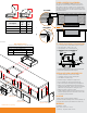
TOP VIEW
SIDE VIEW
(Counter-top)
(Control
panel)
(Overhang)
X
Y
Counter-top
overhang
Control
panel
X= 1/2”
Y= Total
counter-top
overhang
ISLAND COUNTER-TOP OVERHANG
The control panel is designed to sit flush against the enclosure
front wall. If the enclosure counter-top extends beyond the front
wall, creating a counter-top overhang, it must be cut flush with the
front wall for the width of the control panel or a gap will be created
exposing the forward portions of the left and right side grill fire walls.
See illustrations below.
*Available with left or right hinge
“L” SERIES ELECTRICAL SPECIFICATIONS
• “L” Series grills require 120VAC (5 AMP min.) power to operate
• Power supply rating - 120VAC / 0.3A / 60 Hz
• Oven lights rating - 12V / 10 watt halogen bulb
Left interior
oven light
Right interior
oven light
Backburner
igniter
Main burner
igniters
Igniter
module
Igniter
switch
Light
switch
Lighted bezels
(disconnected)
Ground wire
connection
Power
supply
Wire harness
extension
“L” SERIES BUILT-IN GRILL WIRING DIAGRAM
*
*
24” model shown. Model wire diagrams vary between models, a wire diagram specic
to each unit can be found afxed to the inside of the control panel.