
Installation and Operation


28
CHECKING/CONVERTING THE BURNER ORIFICES (Cont.)
ADJUSTING YOUR BARBECUE
Important: This appliance may not light or heat
evenly or cook properly unless the
air shutters are adjusted following
installation (see AIR SHUTTER
ADJUSTMENT section).
Burner air shutters are easily accessed by removing
the control panel. See the CONTROL PANEL
REMOVAL section for access.
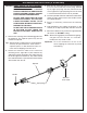
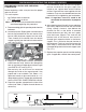
The air shutters are located on the front portion of
each burner and have a locking screw that prevents
the air shutter from inadvertent movement (see
Fig. 28-1).
Remove the cooking grids & vaporizer panels from
the barbecue.
To close or open the
air shutters, simply
loosen the locking
screw, using a long
stemmed Phillips
screwdriver, and
turn the air shutter
to open or close it.
Tighten the screws
down when the
desired setting is
achieved.
MAIN BURNER AIR SHUTTER ADJUSTMENT
Light the burner to be adjusted in accordance with
the LIGHTING INSTRUCTIONS and burn for 2
minutes with the burner control knob set to HIGH
and the oven open. After burning for 2 minutes,
open the air shutter until the fl ames lift off, or appear
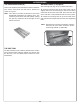
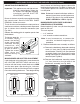
not to be touching the burner. Then begin closing
the air shutter until the fl ames appear to burn while
touching the burner ports (Fig.
28-2). If fl ames are
a lazy yellow, open the air shutters until the fl ame
is mostly blue.
Note: Barbecues in some installations achieve a
better air/gas mixture and will ignite more
quickly if the valve is fi rst turned beyond
HIGH to MEDIUM or LOW for lighting.
BACKBURNER ORIFICE SIZE CHECKING/
CONVERSION (IF EQUIPPED)
Before beginning, make sure you have the proper
tools for the task.
This task requires:
• a
1
/
4"
nutdriver
• a
3
/
8"
wrench or socket screwdriver
Note: It may be necessary to remove the
rotisserie rod before beginning this
procedure.
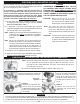
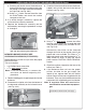
1. Remove the backburner assembly as follows:
a. Remove the backburner electrode mounting
screw (
1
/
4
" hex) (see Fig. 28-3) and loosen
the electrode. Carefully pull the electrode
assembly slightly from the grill wall to give
enough clearance for the backburner to be
removed (see Fig. 28-4).
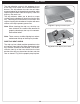
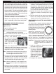
b. Remove the backburner mounting screws
(
1
/
4
" hex) located at the left end of the
backburner assembly (see Fig. 28-5).
Fig. 28-1
Locking
screw
Air shutter
Fig. 28-2 - Flame appearance diagram
Flame off ports
Flame on ports
Procedure continued on next page
Fig. 28-5 Remove backburner mounting screws
Remove
backburner
screws
Fig. 28-3 Fig. 28-4