
Installation and Operation


30
CHECKING/CONVERTING THE BURNER ORIFICES (Cont.)
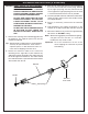
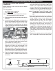
7. After checking the orifi ce drill size or replacing
the orifi ce, replace the infrared burner over the
orifi ce fi tting, sliding it forward, from behind the
forward fi re wall, so the orifi ce is centered inside
the burner gas inlet, and set it gently onto the
burner support. The tabs on the bottom back of
the burner must each fi t through their respective
slots in the burner support. This is critical to the
safe function of the barbecue.
8. Reconnect the ignitor wire to the bottom of the
electrode assembly on the infrared burner.
9. Replace the vaporizer panels and the cooking
grids. If applicable, reinstall the control panel.
6. Re-insert the cotter pin underneath the sideburner
assembly using needle-nose pliers. It may be
necessary to push downward on the burner
assembly from above to fully expose the cotter
pin hole. Rotate the inserted cotter pin so that it
is fl ush with the underside of the shelf.
7. Replace the burner cap by centering it on the
sideburner assembly and making sure it drops in
place.
8. Replace the grill with the grating running front to
back so that it drops fully down onto the shelf,
allowing the lid to close completely over it.
SIDEBURNER AIR SHUTTER ADJUSTMENT (IF
EQUIPPED)
The fl ames from a properly adjusted sideburner will
touch the burner ports and appear mostly blue.
If the fl ames are orange, “lazy”, or
lift off the burner ports, then adjust
the sideburner air shutter using the
following steps.
Sideburner adjustment is the
most accessible (not requiring
any hardware to be removed fi rst)
and is located underneath the
sideburner shelf on the left side of the barbecue, near
the wall of the cart. The sideburner air shutter can
safely and easily be adjusted while the sideburner is lit.
CAUTION: Do not touch the sideburner or the shelf
immediately around it. They will be
hot while adjusting the sideburner air
shutter.
1. Light the sideburner following the lighting
instructions in this manual.
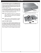
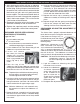
2. Loosen the sideburner
air-shutter adjustment
screw, then use the tip
of the screwdriver to
open or close the air
shutter until the fl ames
appear blue and touch
the burner ports.
3. Re-tighten the adjustment screw.
SIDEBURNER ORIFICE SIZE CHECKING/
CONVERSION (IF EQUIPPED)
Suggested Tools:
• a pair of needle-nose pliers
• a
5
/
16
" hex nut driver
Note: It may be necessary to remove the rotisserie
rod before beginning this procedure.
1. Lift the sideburner lid. Then remove the grill and
sideburner cap and set them aside.
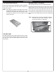
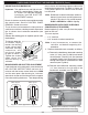
2. Locate and remove
the cotter pin from the
sideburner assembly
underneath the sideburner
shelf using needle-nose
pliers (Fig. 30-2). Set it
aside.
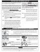
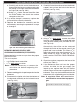
3. From the top of the
sideburner shelf lift the sideburner upward while
rotating the attached tubing underneath away from
the orifi ce near the cart wall. Set it aside.
Note: To protect the manifold threads when placing
the new orifi ce, start the threading manually,
and then tighten with the nut driver.
4. Use the nut driver to remove the exposed orifi ce
and replace it with the correct orifi ce for the gas
being converted to. (see Table 1 for correct orifi ce
sizes based on burner type and gas type).
Note: While the sideburner is still removed it may
be convenient to adjust the sideburner air
shutter.
5. Rotate the burner assembly back into place over
the orifi ce so that the orifi ce is centered deeply
into the burner pipe and the burner fi rmly seated
in the shelf.
Fig. 30-4
Close
Open
Fig. 30-3
Fig. 30-2
Cotter
pin