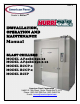
REV. E Cooler is Better!TM INSTALLATION, OPERATION AND MAINTENANCE Manual BLAST CHILLERS MODEL AP40BC250-12 MODEL AP40BC250-2-12 MODEL BCCP-1 MODEL BCCP-2 MODEL BCIP American Panel Corporation 5800 S.E. 78th Street, Ocala, Florida 34472-3412 Phone: (352) 245-7055 Fax: (352) 245-0726 E-mail: service@americanpanel.
Thank you, and congratulations on your purchase of an American Panel blast chiller. We take great pride in engineering and manufacturing each of our products. With the goal of providing the highest accuracy and quality possible, our state-of-the-art manufacturing and quality control facility enables us to continually explore new technologies so that we can provide you with the finest equipment in the industry.
INDEX Index Index ....................................................................................................................................................................................... 1 A. Introduction ......................................................................................................................................................................... 3 A.1. Controller Features................................................................................................
INTRODUCTION F.4. Printer Maintenance.................................................................................................................................................... 50 F.5. Replacing The Ribbon (No Paper In The Printer)....................................................................................................... 50 F.6. Replacing The Ribbon (With Paper In The Printer) .................................................................................................... 50 G.
INTRODUCTION A. Introduction The Models AP40BC250-12, AP40BC250-2-12, BCCP-1, BCCP-2, and BCIP Blast Chillers are used to rapidly chill cooked foods to temperatures suitable for storage in a refrigerator. Blast chillers are sophisticated refrigeration machines capable of lowering the core temperature of most foods from 160°F to 38°F in less than two hours.
INTRODUCTION A.1.2. Operating Cycles The operator can choose from the following 6 operating cycles: MODE SOFT CHILL HARD CHILL FOOD TEMP. AT END 38o F TO 40o F 38o F TO 40o F SHOCK FREEZE N/A USES NOTES: FOR LOW DENSITY FOODS FOR MEDIUM & HIGH DENSITY FOODS AIR TEMP. IS 28o F TO 35o F AIR TEMP. STARTS AT 0o F, RISES TO 28o F TO 35o F WHEN FOOD CORE TEMP.
CONTROLLER 5
INSTALLATION B. Installation American Panel Corporation equipment has been shipped in a package designed to sufficiently protect from damage under normal shipping circumstances. Upon receiving the shipment, carefully inspect the package for visible damage and check the number of packages against the Bill of Lading. Notify the carrier immediately of any shortage or damage to your shipment. Claims must be filed promptly with the carrier.
INSTALLATION Control Panel with Connection Cables 1 Ea for BCCP-1, BCCP-2, AP40BC250-12, and AP40BC250-2-12 2 Ea for BCIP Drain Pan 1 Ea for BCCP-1 and AP40BC250-12 2 Ea for BCCP-2, BCIP, and AP40BC250-2-12 Top Air Deflectors 2 Ea for BCCP-1 and AP40BC250-12 4 Ea for BCCP-2, BCIP, and AP40BC250-2-12 Ceiling Panel with Mounted Light Fixture 1 Ea for BCCP-1 and AP40BC250-12 2 Ea for BCCP-2, BCIP, and AP40BC250-2-12 Ceiling Panel Trims 1 Ea for BCCP-1 and AP40BC250-12 2 Ea for BCCP-2, BCIP, and AP40BC250-2
INSTALLATION B.2. Initial Cabinet Preparation Note: Refer to the assembly drawing attached to the back of this manual to determine the location of the components inside the cabinet, the location of the drain line and the location of the controller. Check if the cabinet was provided with penetrations to accommodate the refrigeration pipes (2-1/2” hole), the drainpipe (11/2” hole), and the controller (7-1/2” x 3-1/2”).
INSTALLATION 3. Cut penetration for the control panel and cables Refer to the assembly drawing attached to the back of this manual to find the location of the control panel. Establish the location of the controller on the cabinet and cut a penetration of 7-1/2” x 3-1/2” to accommodate the cables and the cable duct. 4. Install air deflectors Install the air deflectors on the top corners (above the fan and coil frames) using the provided self-taping stainless steel screws (see DRAWING B.3.1) B.3.
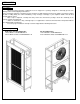
INSTALLATION DRAWING B.3.1 DRAWING B.3.2 3. Install the fan assembly frame Insert the fan assembly frame into the cabinet at the location indicated in the assembly drawing attached to the back of this manual. Push the assembly tight to the side wall leaving ¼” space at the front and rear panels. 4. Adjust the seal brackets on the fan assembly frame (see DRAWING B.3.3) DRAWING B.3.
INSTALLATION 5. Adjust the feet Adjust the feet on the fan assembly and coil assembly frame to raise the frames as high as possible and to level the frames. Make sure the fan assembly and the coil assemblies are at the same level, when installing the ceiling panel, it will have to be level (see step 10 of this procedure). DRAWING B.3.
INSTALLATION 6. Secure the frames Secure the fan assembly frame and the evaporator assembly frame to the cabinet walls using the provided holes at the top-back of the frames (see DRAWING B.3.5 and DRAWING B.3.6 respectively). DRAWING B.3.5 DRAWING B.3.6 7. Install the drain pan 8. Install the control panel Insert the cables and connectors thru the pre-cut penetration (see chapter B.2, step 3 page 9) and push the control panel to mate it to the cabinet.
INSTALLATION 9. Make the electrical connections (see chapter B.3.1, page 14) 10. Install the ceiling panel Lower the ceiling panel onto the frames, make the plug and connector connection and secure the ceiling panel onto the fan assembly and coil assembly (see DRAWING B.3.8). DRAWING B.3.
INSTALLATION B.3.1. Electrical Connections All power cables inside the cabinet, with the exception of door / window heater and door switch cables, are provided with twist and lock plugs and connectors. All cables, plugs, and connectors are color coded. (see Color Code Chart below).
INSTALLATION PHOTO B.3.1.2 According to the color code chart, the orange coded cable is for the door / window heater. Connect this cable with the door and window heaters inside the connection box provided by the box supplier. Connect the brown cable with the door switch using heat shrink butt splices. NOTE: If the door switches are not installed by the box supplier, mount the ones provided by American Panel Corporation as shown in DRAWING B.3.1.1 and DRAWING B.3.1.2 at page 16. DRAWING B.3.1.
INSTALLATION DRAWING B.3.1.2 NOTE: Route the micro-switch wires through the wall and bring them inside the cabinet at approx. 6” above the door. Insulate the wall hole(s) with silicone, expandable foam, or grommets. Take precaution to protect the heater wires inside the door frame. Provide a J-Box to connect the wires. The thermocouple cables (gray) are provided for the air probe(s) and the food probe(s).
INSTALLATION B.4. Install The Thermostat Bulb Remove the evaporator filter side trim that supports the probes to access the back of evaporation frame, see DRAWING B.3.1., page 10. Install the thermostat bulb on the coil assembly frame as close as possible to the defrost heaters, but not closer than 5”, see PHOTO B.4.1. Secure the bulb with cable ties to minimize risk of breakage of the capillary tube caused by vibration. PHOTO B.4.
INSTALLATION PHOTO B.3.1.3 B.5. BCIP Installation BCIP BCIP model is comprised of two adjacent BCCP-1 units. Follow the instructions from the previous chapters to install BCIP.
INSTALLATION B.6. Double Unit Installation AP40BC250-2-12, BCCP-2 BCCP-2 Installation procedures are similar with the ones for the single unit. Each of the two evaporators is fed by one condensing unit. A double unit has two evaporator frames (one per compartment) and two blower frames (one per compartment) controlled by a single control panel. The difference is made by the double number of power cables and air probe cables. The two frames to be installed by the control board are marked # 1.
INSTALLATION PHOTO B.5.2 C. Refrigeration Unit Installation C.1. Preparation Check the integrity of the unit once it is unpacked Check to make sure the floor is leveled Check that the available power supply corresponds to the ratings on the unit’s nameplates and correctly rated electrical protection is provided. If additional refrigerant should be needed, be certain to use the correct type. Make certain that adequate drainage is provided.
INSTALLATION C.3. Refrigeration Lines Installation Follow the steps below to assure a proper installation. 1. Minimum pipe inclination has to be provided. CONDENSING UNIT 2. Make sure you place the fastening brackets on insulated piping. 3. Provide air tight welding. 4. Create the vacuum and load the line. 5. 6. 7. 8. Check for leaks. Open the shut-off valves (A & B) on both sides of remote unit and of cabinet. Check the exact load of refrigerant in the liquid passage gauge.
INSTALLATION Use the table below to determine the number of pipe supports you need to install. Distance (ft.) 16 32 48 64 80 Number of Pipe Supports 2 3 5 7 9 C.3.1. Installation At The Same Level If the condensing unit is going to be installed at the same level with the cabinet, follow the instructions in the DRAWING C.3.1.1 DRAWING C.3.1.1 C.3.2. Installation At Different Levels If the remote condensing unit is installed at a higher level than the cabinet (DRAWING C.3.1.
INSTALLATION C.4. Connect The Remote Unit The specified piping diameters (see chart below) from the remote condensing unit to the cabinet is adequate for a separation of up to 60 feet. For greater distances, contact the factory for instructions. Supply Line Intake Line Diameter of Copper Piping ½” 1 1/8” **Note: The insulation used on the piping must be of high quality and must have closed cells. CONDENSATE DRAINAGE CONNECTION It is important that condense from the evaporator is properly drained.
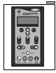
PROGRAMMING D. Programming The Controller WARNINGS! Read and carefully follow all of the instructions in this manual before attempting to install this equipment. Installation must be performed by a qualified Service Agency approved and authorized by American Panel Corporation. Doing otherwise may void the warranty. Any changes made to the equipment without authorization from the factory will void the warranty. All American Panel Corporation blast chillers are initially programmed at the factory.
PROGRAMMING o With the display reading "OFF", press (”UP”) for 10 seconds Clear events memory state – to clear obsolete data o (“A”) for 10 seconds Load default values state – to load the standard parameters o With the display reading "OFF", press With the display reading "OFF", press + (”UP”+”DOWN”) for 10 seconds Ready To Go state – in order to start a cycle o If the controller is not "OFF", press “ON/OFF” once. D.3.
PROGRAMMING If the entered password is wrong the display will show, for 3 seconds: Then the controller will go back to step c. INITIAL PROGRAMMING WRONG PASSWORD TRY AGAIN TRY AGAIN Blinks NOTE: If a wrong password is introduced three times the controller will go into “OFF” state. During the password typing, button can be used to delete one or more characters. d. If you do not wish to change the password, press To change the default password, press "YES" then press or .
PROGRAMMING The high air alarm temperature should be left at 140 oF. However, if a change is desired: k. To change the temperature, press press INITIAL PROGRAMMING or then HIGH AIR ALARM 140 °F 140 Blinks . The low air alarm temperature should be left at -5 oF *. However, if a change is desired: l. To change the temperature, press press INITIAL PROGRAMMING or then LOW AIR ALARM -35 °F * -35 Blinks . INITIAL PROGRAMMING m.
PROGRAMMING If you selected YES at the previous step, the next steps will allow you to setup the thaw cycle. If you selected NO, skip to step y. s. To change the final temperature of the food to be thawed, press or then press . t. To change the maximum air temperature during the thaw cycle, press or then press . u. To change the minimum air temperature during the thaw cycle, press or then press . v. To change the maximum air temperature during the hold cycle, press or then press . w.
PROGRAMMING INITIAL PROGRAMMING cc. To change the timing, press or then press PRINT & SAVE EVENTS EVERY 15 MIN 15 Blinks . INITIAL PROGRAMMING dd. To change to YES or NO, press press or then PRINT DURING CYCLE NO NO Blinks . INITIAL PROGRAMMING ee. To change to YES or NO, press press or then RECIPES? NO NO Blinks . INITIAL PROGRAMMING ff. To change to YES or NO, press press or then NAFEM COMMUNICATION NO NO Blinks .
PROGRAMMING PARAM. PROGRAMMING b. Enter the password (see page 25), then press . The LED for "A" will be "ON". The LED'S for cycles will be blinking. c. Press . The LED for "SOFT" will be steady "ON". d. To change the temperature, press press PARAM. PROGRAMMING AUTOMATIC SOFT CYCLE HIGH AIR TEMPERATURE 35 °F or then 35 Blinks PARAM. PROGRAMMING AUTOMATIC SOFT CYCLE FOOD TEMPERATURE 40 °F or then 40 Blinks PARAM. PROGRAMMING AUTOMATIC SOFT CYCLE HOLDING LOW TEMP.
PROGRAMMING c. Press the steady "ON". button. The LED for "HARD" will be d. To change the temperature, press press or then 60 Blinks or then PARAM. PROGRAMMING AUTOMATIC HARD CYCLE LOW AIR TEMP PART 2 28 °F 28 Blinks or then PARAM. PROGRAMMING AUTOMATIC HARD CYCLE HIGH AIR TEMP PART 2 35 °F 35 Blinks PARAM. PROGRAMMING AUTOMATIC HARD CYCLE HARD FOOD TEMP. 40 °F or then 40 Blinks PARAM. PROGRAMMING AUTOMATIC HARD CYCLE HOLDING LOW TEMP. 35 °F or then 35 Blinks . k.
PROGRAMMING D.5.2. Parameter Programming Manual Mode Note: All American Panel Corporation blast chillers are initially programmed at the factory. These settings may be considered standard for AP40BC250-12, AP40BC250-2-12, BCCP-1, BCCP-2, and BCIP units. However, the customer may change any of these settings as indicated by necessities.
PROGRAMMING q. To change the temperature, press press or then PARAM. PROGRAMMING MANUAL SOFT CYCLE HOLDING HIGH TEMP 42 °F 42 Blinks . PARAM. PROGRAMMING MANUAL SOFT CYCLE The display will show: PROGRAMMING COMPLETE D.5.2.2. Hard Cycle – Manual Mode OFF With the display reading "OFF", press . PARAM. PROGRAMMING Enter the password (see page 25), then press . ENTER PASSWORD *** After about 2 seconds the display will automatically change to: The LED for "A" will be "ON".
PROGRAMMING w. To change the temperature, press press or then PARAM. PROGRAMMING MANUAL HARD CYCLE HIGH AIR TEMP PART 2 35 °F 35 Blinks . x. To change the time, press or then press PARAM. PROGRAMMING MANUAL HARD CYCLE TIME 2 H 01:00 MIN . y. To change the temperature, press press or then 01:00 Blinks PARAM. PROGRAMMING MANUAL HARD CYCLE HOLDING LOW TEMP. 35 °F 35 Blinks PARAM. PROGRAMMING MANUAL HARD CYCLE HOLDING HIGH TEMP. 42 °F 42 Blinks . z.
PROGRAMMING D.5.4. Defrost Cycle Programming OFF With the display reading "OFF", press . PARAM. PROGRAMMING Enter the password (see page 25), then press . ENTER PASSWORD *** After about 2 seconds the display will change to: a. Press the be "ON". button. The LED for "DEFROST" will b. Press or press c. PARAM. PROGRAMMING AUTOMATIC MODE CHOOSE PROGRAMMING CYCLE PARAM. PROGRAMMING DEFROST CYCLE CHOOSE TYPE ELECTRIC to choose “ELECTRIC”, then .
PROGRAMMING D.6. Recipe Name Programming OFF A. With the display reading "OFF", press the and hold it for 10 seconds. button B. Enter your password (see page 25), then press . RECIPES PROGRAMMING ENTER PASSWORD *** C. Press or to change to the desired recipe number (from 1 to 150), then press you to the "NAME" line. D. Using or the next one press . To confirm the recipe and go to . If a mistake is made in writing a recipe, use to go to the desired location and correct it using or .
PROGRAMMING E. Operation E.1. Automatic Mode – Soft Chill OFF a. With the display reading "OFF", press the (“ON/OFF”) button. b. To select the soft cycle, press the appropriate button . The LED for "SOFT" will be steady "ON". c. The LED's for “AUTOMATIC” and “MANUAL” are now blinking. To select an “AUTOMATIC” cycle, press the button . The LED for “AUTOMATIC” will now be steady "ON". d.
PROGRAMMING READY TO START The display will show: PRESS START alternating with alternating with 03.07.2006 AIR 1 10:28 AM 75°F PRESS START Blinks 00:00 h. Press the cycle. ("START/STOP") button to start the R / CHICKEN Y / ROAST BEEF B / CHICKEN G / ROAST BEEF The display will show briefly: STARTING CYCLE . . . Then the display will show: 03.07.
PROGRAMMING E.2. Automatic Mode – Hard Chill OFF i. With the display reading "OFF", press the (“ON/OFF”) button. j. To select the hard cycle, press the appropriate button . The LED for "HARD" will be steady "ON". OPERATING MODE CHOOSE OPERATING CYCLE k. To select an “AUTOMATIC” cycle, press the button HARD CYCLE . The LED for “AUTOMATIC” will now be steady "ON". l.
PROGRAMMING READY TO START The display will show: PRESS START alternating with alternating with 03.07.2006 AIR 1 10:28 AM 75°F PRESS START Blinks 00:00 p. Press the cycle. ("START/STOP") button to start the R / CHICKEN Y / ROAST BEEF B / CHICKEN G / ROAST BEEF The display will show briefly: STARTING CYCLE . . . Then the display will show: 03.07.
PROGRAMMING E.3. Manual Mode – Soft Chill OFF q. With the display reading "OFF", press the (“ON/OFF”) button. r. To select the soft cycle, press the appropriate button OPERATING MODE CHOOSE OPERATING CYCLE . The LED for "SOFT" will be steady "ON". s. To select an “MANUAL” cycle, press the button . SOFT CYCLE CHOOSE MODE AUTO / MAN t.
PROGRAMMING READY TO START The display will show: PRESS START alternating with 03.07.2006 AIR 1 alternating with 10:28 AM 75°F PRESS START Blinks 00:00 x. Press the cycle. ("START/STOP") button to start the R / CHICKEN Y / ROAST BEEF B / CHICKEN G / ROAST BEEF The display will show briefly: STARTING CYCLE . . . Then the display will show: 03.07.
PROGRAMMING E.4. Manual Mode – Hard Chill OFF y. With the display reading "OFF", press the (“ON/OFF”) button. z. To select the hard cycle, press the appropriate button . The LED for "HARD" will be steady "ON". aa. Press the button to select “MANUAL”. The LED for “MANUAL” will now be steady "ON". bb.
PROGRAMMING READY TO START The display will show: PRESS START alternating with alternating with 03.07.2006 AIR 1 10:28 AM 75°F PRESS START Blinks 00:00 ff. Press the cycle. ("START/STOP") button to start the R / CHICKEN Y / ROAST BEEF B / CHICKEN G / ROAST BEEF The display will show briefly: STARTING CYCLE . . . Then the display will show: 03.07.
PROGRAMMING E.5. UV (STERILIZATION) CYCLE a. To perform a UV cycle remove all food, then press the CHOOSE OPERATING CYCLE (“UV LIGHT”) button. b. Press the cycle. OPERATING MODE ("START/STOP") button to start the UV 03.07.2006 11:43 AM UV CYCLE READY TO START The display will show briefly: STARTING CYCLE . . . Then the display will now show: 03.07.2006 11:43 AM UV CYCLE UV TIME After 30 minutes the display will show: The controller will beep for a few seconds.
PROGRAMMING E.6. DEFROST CYCLE The defrost cycle runs the defrost heaters for 30 minutes. OPERATING MODE a. To perform a defrost cycle, press button. b. Press the defrost cycle. ("DEFROST") ("START/STOP") button to start the CHOOSE OPERATING CYCLE 03.07.2006 12:15 PM DEFROST CYCLE READY TO START The display will show briefly: STARTING CYCLE . . . The display will now show: 03.07.
PROGRAMMING E.7. Thaw Cycle (Optional) E.7.1. Food Loading When loading the food into the unit, in preparation for thawing cycle, space the food enough to achieve optimum air circulation within the cabinet. Use the provided food grade drill to drill a hole into the thickest part of the food and fully insert the thaw probe in it. Note: The thaw probe must be fully inserted into the product. E.7.2. Automatic Thaw Cycle OFF a. With the display reading "OFF", press the (“ON/OFF”) button. b.
PROGRAMMING E.7.3. Manual Thaw Cycle OFF a. With the display reading "OFF", press the (“ON/OFF”) button. b. To perform a thaw cycle, press ("DOWN") button. c. The display will show. THAW CYCLE AUTO / MANUAL To change the thaw cycle time press Note: If 06:00 Blinks MANUAL THAW MANUAL THAW TIME H 06:00 MIN d. Press the ("MANUAL") button. The display will now show: press the OPERATING MODE CHOOSE CYCLE or then ("START/STOP") button to start the cycle.
PROGRAMMING E.8. Preparing And Using The Optional Printer OFF a. With the display reading "OFF", press the (“PRINT”) button. b. To start printing, press the button. ("START/STOP") After a few seconds the display will show: and the printer will be printing. PRINT EVENTS MEMORY READINGS LEFT 249 PRINT EVENTS MEMORY PRINTING . . . E.9. Clear Data a. To clear existing data that is no longer needed from the OFF controller, from the "OFF" display, press and together for about 10 seconds.
PROGRAMMING F. Printer F.1. Loading The Paper 1. 2. 3. 4. 5. 6. 7. 8. 9. 10. Remove the paper cover by pressing on the groove patterns to pop the front edge up. Lift off the cover. Press the rocker switch to the left. The light will go off. Unroll several inches of paper. Cut a straight edge on the paper roll if it is jagged. This will facilitate the entry of the paper into the printer.
MAINTENANCE G. Maintenance And Cleaning Warnings: 1. Read all the instructions before you attempt to operate the equipment. 2. Always disconnect the unit from the power source before attempting any service or maintenance. 3. Repairs should be performed by a qualified service agency approved by American Panel Corporation. 4. Any changes made to the equipment without the written authorization from the factory will void the warranty. Daily Cleaning: 1. Before starting, remove the plug from the wall.
WARRANTY H. Standard Warranty AMERICAN PANEL CORP. 5800 S.E. 78th Street, Ocala, Florida 34472-3412 American Panel Corporation products are warranted to the original user installed within the United States and Puerto Rico to be free from defects in materials and workmanship under normal use and service for the applicable period shown in the chart below. NOTE: This Warranty does not apply to altered or misused parts.
APPENDIXES I.
APPENDIXES I.1.
APPENDIXES J. Appendix 3 Parts List Part Number Description 990066 991011 991007 994085 Solenoid Coil Assembly for EVR 208/240 50/60Hz 17.5W Junc. Solenoid Valve EVR6 Excl. Coil 1/2 ODF Filter Drier 1/2" SAE Condensing Unit 991005 990042 990083 992025 992001 991006 990047 990076 990049 991012 990060 990059 990074 990075 990190 990188 990184 1098 990052 990013 990218 Evaporator Coil (Stainless Steel Frame) Heaters, Coil Tblr. 390W TH-7349-1687 Fan motor Fan blades (REV 00-F10H87 1825 .
APPENDIXES J.1. Appendix 4 Ordering Printer Supplies (Ribbon & Paper) Replacement paper and ribbons for the printer supplied with your blast chiller can be ordered from a local distributor of Weigh-Tronix supplies. To locate a distributor near you: If you have access to the internet: Go to www.wtxweb.com Click on Sales & Service Click on Dealer Locator Enter your zip code or city / state If you do not have access to the internet: Call American Panel Corp.
American Panel Corporation 5800 S.E. 78th Street, Ocala, Florida 34472-3412 Phone: (352) 245-7055 Fax: (352) 245-0726 E-mail: service@americanpanel.