APC Silcon 10-40kW 208/480V UPS User Guide Copyright ©2000 APC Denmark ApS Information in this document is subject to change without notice and does not represent a commitment on the part of the vendor
Thank You Thank you for chosing APC Silcon. Please read this User Guide thoroughly prior to installing the system as it provides important information on safe and efficient installation and use. The installation and use of this product must comply with national, federal, state, municipal and local codes. Safety Symbols used in this manual WARNING! Indicates a hazard which, if not avoided, could result in injury or death.
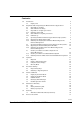
Contents: 1.0 Introduction 1.1 Display Unit 4 4 2.0 Stop/Start UPS and Operating the External Service Bypass Panel 2.1 Stop UPS (for stand-by) 2.2 Start UPS (from stand-by) 2.3 Stop UPS (for complete power down) 2.3.1 Switching off the UPS 2.4 Start UPS (from complete power down) 2.4.1 UPS start-up 2.5 Operating the External Service Bypass Switch (single systems) 2.5.1 Bypassing the Single System UPS 2.5.2 Switching the Single System UPS from External Bypass into Normal UPS Operation 2.
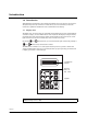
Introduction 1.0 Introduction This UPS system is designed to offer reliable and problem-free power supply for several years. The system requires only a minimum of maintenance, but we recommend you follow the maintenance guidelines described in section 6.0 Maintenance & Testing. 1.1 Display Unit The display unit (located on the front of the UPS) is the link between the user and the UPS and consists of a display, an alarm LED indicator and a keyboard.
Stop/Start UPS and Operating the External Service Bypass 2.0 Stop/Start UPS and Operating the External Service Bypass Panel WARNING! AC voltage generated either from batteries or utility may be present at UPS output. Always disconnect AC input supply source, switch off UPS, AND switch off DC. TEST BEFORE YOU TOUCH! Some UPS systems have a factory-set autostart feature, automatically switching on UPS whenever utility supply is switched on (AC line). See section 4.
Stop/Start UPS and Operating the External Service Bypass 2.3 Stop UPS (for complete power down) 2.3.
Stop/Start UPS and Operating the External Service Bypass The UPS is now isolated. Maintenance/repair, disconnection or removal can now be carried out. CAUTION! Recharge batteries out of service every 3 months to prevent damage. WARNING! Internal DC capacitor may contain energy even after the UPS has been switched off. Allow for automatic discharge by waiting at least 5 minutes after switching off UPS and battery breakers before working on the UPS. 2.4 Start UPS (from complete power down) 2.4.
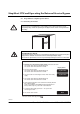
Stop/Start UPS and Operating the External Service Bypass 1. Check that the system has been in a stable environment for at least 12 hours enabling any condensation to evaporate prior to start-up. 2. Open front door(s) Display shows 3. Switch on utility power by closing Q001 If dual utility close bypass input switch Q010 See notice below. System type XXX XXX kVA - XXX 4. Wait for approx. 10 seconds Stop charge DC capacitors : YES 5. Press on the keyboard Start charge DC capacitors : YES 6.
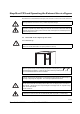
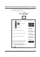
Stop/Start UPS and Operating the External Service Bypass 2.5 Operating the External Service Bypass Switch (single systems) 2.5.1 Bypassing the Single System UPS Load Utility Service Bypass Switch APC Silcon UPS Display shows Action 1. Press on the keyboard 2. Press or 3. Press on the keyboard 4. Press on the keyboard on the keyboard until Bypass operation : NO Bypass operation : YES Lamp indication on Bypass Panel 5.
Stop/Start UPS and Operating the External Service Bypass CAUTION! Do not leave UPS out of service for more than 48 hours. Refer to section 2.3 Stop (for complete power down). 2.5.
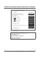
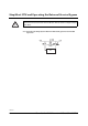
Stop/Start UPS and Operating the External Service Bypass Action Display shows 1. Set the input switch (Q001) to position 1 2. Wait 5 sec. Open the front door of the UPS and press the green ON key 3. Press on the keyboard 4. Press or 5. Press on the keyboard 6. Press on the keyboard on the keyboard until **System OFF** Normal operation load power 0% Bypass operation : NO Bypass operation : YES Lamp indication on Bypass Panel 7.
Stop/Start UPS and Operating the External Service Bypass 2.6 Operating the External Service Bypass Switch (parallel systems) 2.6.1 Bypassing the Parallel UPS System (All UPSs) Utility Load Service bypass switch APC Silcon UPS APC Silcon UPS CAUTION! Do not leave UPS out of service for more than 48 hours. Refer to section 2.3 Stop (for complete power down).
Stop/Start UPS and Operating the External Service Bypass Action Steps 1-4 apply to all the parallel systems. Note that this will switch all systems into bypass operation 1. Press on the keyboard 2. Press or 3. Press on the keyboard 4.
Stop/Start UPS and Operating the External Service Bypass 2.6.2 Switching the Parallel System from External Bypass into Normal UPS Operation Utility Load Service bypass switch APC Silcon UPS APC Silcon UPS NOTICE! If battery has been disconnected, please refer to section 2.4.1 UPS start-up.
Stop/Start UPS and Operating the External Service Bypass Action Display shows 1. Check that the output switch (Q004) is set to position 0 2. Check that all output switches (Q002) are set to position 1 3. Set input switches (Q001) to position 1 4. Wait 10 secs. Open the UPS front door and press the green ON button on all systems 5. Press on the keyboard 6. Press or 7. Press on the keyboard 8.
Stop/Start UPS and Operating the External Service Bypass 2.7 Isolating one UPS in a Parallel Configuration for Service/Maintenance 2.7.1 Isolating one UPS in a Parallel/Redundant System Utility Load Service bypass switch APC Silcon UPS APC Silcon UPS In a redundant system one UPS may be isolated for service/maintenance without affecting other parallel UPS(s). Action 1. Check that the remaining UPS(s) will be able to carry the load when one UPS is isolated. 2.
Operation 3.0 Operation The display unit will read parameters, alarms/messages and measured values. LED alarm incorporates audible alarm, indicating unusual operating situations. The keyboard is used to program and control parameters and to display alarm messages and measured values. 3.
Operation 3.2 Display of Measured Values To read measurements, press one or two keys simultaneously as shown below. (Illustrated values are examples only). NOTICE! Please note mains = utility Action Display shows 98.01.16 System off 10.
Operation 3.3 Using the Remote Display The remote display is an inactive unit that is unable to influence the operation of the APC Silcon UPS. It is impossible to adjust or otherwise influence the function of the UPS. The alarms available on the remote display are at subset of the alarms, which can be read on the internal display. • Operation of Remote Display is described in section 3.0 above. • Alarms available are described in section 5.0 Alarms. • Readout of measurements as described in section 3.
Parameter Settings 4.0 Parameter Settings Below tables show operating parameters programmable from keyboard. Only qualified users should alter programming parameters. See below examples. Parameter Settings Parameter Setting* Comments Bypass operation YES, NO YES will switch the system into bypass mode*** Language GB, D, F, DK, S, SF, NL, PL, CZ, E, P, SK, H Languages of text in display Autostart YES, NO Automatic restart by utility return (1 min. delay). Ensures quick battery recharge.
Parameter Settings 4.1 Programming Keys Scrolls up through list Scrolls down through list 4.2 Displays time Stores parameters/enters parameter stack Return to normal window Silences the audible alarm Accesses the alarm stack Chooses or changes parameters Switching to Bypass Operation Programming Example Display shows Action 1. Press to enter parameter stack 2. Press or 3. Press until 4. Press to store 5.
Parameter Settings To return to normal operation Display shows Action 6. Press to enter parameter stack 7. Press or 8. Press until 9. Press to store 10. Press to exit until Bypass operation : YES Bypass operation : NO Normal operation load power xx% Follow same procedure to program other parameters.
Alarms and Events 5.0 Alarms and Events Alarms are indicated by the red lamp (above the left hand corner of the keyboard) and a 30 seconds acoustic signal. An alarm is registered in the alarm stack as long as it is present, and if more in the same order as they arise. Certain alarms, such as battery alarms, need resetting. See section 4.0 Parameter Settings. All alarms are also registered in an event logger and remains there in a stack with room for 250 events.
Alarms and Events 5.2 Displaying the Event Stack Action 5.3 Description 1. Press and Press the two keys simultaneously to get access to the events stack 2. Press or Scroll up or down through the event stack (last message is "No (further) event"). 3. Press Displays the time where the event happened. 4. Press Exits the event stack. If not operated the system will exit the event stack automatically after 30 seconds.
Alarms and Events 11. Inverter current limiter active Inverter overload Reduce UPS output load 12. Overload. Load exceeding 100% UPS overload Reduce UPS output load 13. Second power supply fault UPS fault (only systems > 160kW) Call for assistance 14. Internal power supply fault UPS fault. Only bypass operation possible Call for assistance 15. Battery MCCB is off Battery MCCB/fuse not closed or released Close MCCB / insert new fuse. If released again call for assistance. 16.
Alarms and Events 34. Output outside tolerance Output voltage outside tolerance Call for assistance 35. Output frequency outside tolerance Output frequency outside tolerance Call for assistance 36. High battery temperature Battery ambient temperature too high Check system ambient temperature, check fan, check for airflow obstructions 37. Battery weak Battery capacity below 75% or battery MCCB/fuse switched off Test battery capacity 38.
Alarms and Events 5.4 Rectifying Alarm Messages Following actions may rectify alarm: • Check local utility supply. Fuses may be blown or supply switched off accidentally • Check if UPS cooling air intake is blocked • Check if load exceeds maximum output capacity • If, with utility power switched on, there is no UPS output voltage - and an attempt to restart the UPS is in vain - use the external service bypass switch to bypass UPS 1.
Maintenance & Testing 6.0 Maintenance & Testing UPS maintenance should be carried out by trained service engineers only. Service and maintenance contract is recommended. 6.1 Fan It is recommended to replace fans every 3 years. 6.2 Battery Monitoring Test Systems with built-in batteries have a standard battery monitoring feature (optional in other systems). Battery Test Results: 1. Battery OK. Back-up time normal. 2. Reduced battery capacity - “Battery weak” message appears. 3.
Maintenance & Testing Display shows Action Description 1. Press 2. Press or Battery capacity test : xxx "xxx" is back-up time from last test – if no previous test has been performed or if the test has been aborted the display will read"???"! A battery monitor test can be performed in the same way by selecting "Battery monitor test" in the display. However, this test will not start, unless the battery is fully charged 3.
Warranty 7.0 Warranty 7.1 APC Silcon UPS Limited Factory Warranty APC warrants that the unit, when properly installed and commissioned by APC or APC authorized service personnel, shall be free from defects in materials and workmanship for a period of (1) year from the date of installation or maximum 18 months after manufacturing.
How to Contact APC 8.0 How to Contact APC APC Corporate 132 Fairgrounds Road West Kingston, RI 02892 USA Telephone: 401 789-5735 Fax: 401 789-3710 PowerFax™: 800 347-FAXX Pre-sales Technical Support 877-474-5266 (1-877-4Silcon) Post-sales Technical Support 877-287-7835 (1-877-2UPS-TEK) Web: www.apcc.com/support/contact/contact_support.