User Manual English APC Smart-UPS® RT – UXI/UXICH 8000/10000 VA 220/230/240 VAC Tower/Rack-Mount 6U Uninterruptible Power Supply 990-2687B 04/2006
Introduction The APC Smart-UPS® RT is a high-performance, uninterruptible power supply (UPS) that provides protection for electronic equipment from utility power blackouts, brownouts, sags and surges. The UPS filters small utility line fluctuations and isolates electronic equipment from large disturbances by internally disconnecting from utility line power. The UPS provides continuous power from the internal battery until utility power returns to safe levels or the battery is fully discharged.
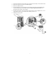
ATTACH THE BEZEL TO THE UPS HARDWIRING INSTRUCTIONS • Wiring must be performed by a qualified electrician. • Adhere to all national and local electrical codes. • Install a utility circuit breaker for input wiring, (see tables below). 220/230/240 V MODELS Input Connections Output Connection (optional) Single-Phase: Wire to L1, N, and Three-Phase: Wire to L1, L2, L3, N, and System SURT8000 SURT10000 Wire to L1A, N1, and . . .
1. 2. 3. 4. 5. 6. Switch the UPS input circuit breaker (see A in diagram) and utility circuit breakers OFF. Remove the input access panel, (see B in diagram). Remove circular knockout. Run appropriate size wire through the access panel, and connect to the terminal block, (Green: Ground, Brown: Hot, Blue: Neutral). Connect the ground wire first. Use appropriate strain reliefs, (not included). For three-phase input, set the input phase selector switch, (see C in diagram) to “3”.
CIRCUIT BREAKERS 8000/10000 VA Input Circuit Breaker The input circuit breaker must be switched on for the UPS to operate. The input circuit breaker protects the UPS from extreme overload conditions. 8000/10000 VA Output Circuit Breakers IEC 320-C13 10 A total current from four receptacles IEC 320-C19 16 A for each receptacle BASIC CONNECTORS Serial Com Power management software and interface kits can be used with the UPS. Use only interface kits supplied or approved by APC.
CONNECT THE EXTERNAL BATTERIES Battery Safety Read and adhere to the following warnings when installing or servicing the external batteries. Failure to observe these warnings may result in serious injury, death or damage to the equipment. WARNINGS • Do not attempt to install or service external batteries alone. A qualified electrician should perform the installation and servicing of external batteries. • Disconnect charging source(s) BEFORE connecting or disconnecting battery terminals.
THIRD PARTY BATTERY SOLUTION Batteries must be Sealed Lead-Acid type. Use 50 A, 250 VDC fuses with an Interrupt rating of ≥ 20,000 A. Ensure that the external batteries are wired prior to connecting the batteries to the UPS. Two separate, isolated 192 V battery systems are required when using a third party battery solution. One cable assembly must be wired to each 192 V battery system. Two cable assemblies are included with the UPS, one for each 192 V battery system.
CONNECT EQUIPMENT AND POWER TO THE UPS 1. Connect equipment to the UPS. 2. Turn on all connected equipment. To use the UPS as a master ON/OFF switch, ensure all connected equipment is switched ON. The equipment will not be powered until the UPS is turned on. 3. Switch the utility circuit breaker on. 4. To power up the UPS press the 5. button on the front panel. • The UPS battery charges when it is connected to utility power.
TERMINAL MODE TO CONFIGURE UPS PARAMETERS AND PROGRAM THE NUMBER OF BATTERY PACKS Terminal Mode is a menu driven interface that enables enhanced configuration of the UPS. Connect the serial cable from the computer to the serial com connector on the back of the UPS. Instructions for use with PowerChute Network Shutdown software: 1. 2. 3. Open a terminal program. Example: HyperTerminal • From the Desktop, go to Start => Programs => Accessories => Communication =>HyperTerminal.
OPERATION SMART-UPS RT FRONT DISPLAY Load Battery Charge Indicator Description Online The Online LED illuminates when the UPS is drawing utility power and performing double conversion to supply power to connected equipment. On Battery The UPS is supplying battery power to the connected equipment. Bypass The Bypass LED illuminates indicating that the UPS is in bypass mode. Utility power is sent directly to connected equipment during bypass mode operation.
Feature Function Normal/Bypass Manual bypass enables the user to manually put connected equipment into bypass mode. While in bypass mode the utility power bypasses the UPS and goes directly to the connected equipment. Battery operation is not available while the UPS is in bypass mode. Refer to Troubleshooting in this manual. Cold Start This is not a normal condition. When there is no utility power and the UPS is off, press and hold the to power up the UPS and connected equipment.
USER CONFIGURABLE ITEMS NOTE: SETTINGS ARE MADE THROUGH SUPPLIED POWERCHUTE SOFTWARE, SMART SLOT ACCESSORY CARDS, OR TERMINAL MODE. FUNCTION FACTORY DEFAULT USER SELECTABLE CHOICES DESCRIPTION Automatic Self-Test Every 14 days (336 hours) Every 7 days(168 hours), 14 days (336 hours) On Startup Only, No Self-Test Set the interval at which the UPS will execute a self-test. UPS ID UPS_IDEN Up to eight characters to define the UPS Uniquely identify the UPS, (i.e.
NOTE: SETTINGS ARE MADE THROUGH SUPPLIED POWERCHUTE SOFTWARE, SMART SLOT ACCESSORY CARDS, OR TERMINAL MODE. FACTORY DEFAULT FUNCTION USER SELECTABLE CHOICES DESCRIPTION High Bypass Point +10% of output voltage setting +5%, +10%, +15%, +20% Maximum voltage that the UPS will pass to connected equipment during internal bypass operation.
CONNECT THE EPO (EMERGENCY POWER OFF) The output power can be disabled in an emergency by closing a switch connected to the EPO. Adhere to national and local electrical codes when wiring the EPO. Wiring must be performed by a qualified electrician. The switch should be connected to a normally open switch contact. External voltage is not required; the switch is driven by 12V internal supply.
MAINTENANCE, SERVICE Battery Replacement See your dealer or contact APC at the Web site, www.apc.com for information on replacement battery modules. Service If the UPS requires service do not return it to the dealer. Follow these steps: 1. Review the problems discussed in the Troubleshooting section of this manual to eliminate common problems. 2. If the problem persists, contact APC Customer Support through the APC Web site, www.apc.com. 3.
TROUBLESHOOTING Use the table below to solve minor installation and operation problems. Refer to the APC Web site, www.apc.com, for assistance with complex UPS problems. PROBLEM AND POSSIBLE CAUSE SOLUTION UPS WILL NOT TURN ON Battery not connected properly. button not pushed. Check that the battery connectors are fully engaged. Press the button once to power the UPS and the connected equipment. UPS not connected to utility power supply.
PROBLEM AND POSSIBLE CAUSE SOLUTION BYPASS LED ILLUMINATES The bypass switch has been turned on manually or through an accessory. If bypass is the chosen mode of operation, ignore the illuminated LED. If bypass is not the chosen mode of operation move the bypass switch on the back of the UPS, to the normal position. FAULT AND OVERLOAD LEDS ILLUMINATE, UPS EMITS A SUSTAINED ALARM TONE The UPS has ceased sending power to connected equipment.
REGULATORY AND WARRANTY INFORMATION Regulatory Agency Approvals and Radio Frequency Warnings 220, 230, 240 V MODELS This equipment has been tested and found to comply with the limits for a Class A digital device, pursuant to Part 15 of the FCC rules. These limits are designed to provide reasonable protection against harmful interference when the equipment is operated in a commercial environment. This equipment generates, uses, and can radiate radio frequency energy.
Declaration of Conformity 18
APC Worldwide Customer Support Customer support for this or any other APC product is available at no charge in any of the following ways: • • Refer to the APC Web site to access documents in the APC Knowledge Base and to submit customer support requests. • www.apc.com (Corporate Headquarters) Connect to localized APC Web sites for specific countries, each of which provides customer support information. • www.apc.com/support/ Global support searching APC Knowledge Base and using e-support.