Symmetra MW UPS w/ Internal Bypass Static Switch User Guide
Contents Safety ......................................................................1 IMPORTANT SAFETY INSTRUCTIONS - SAVE THESE INSTRUCTIONS . . . . . . . . . . . . . . . . . . . . . . . . . . 1 Symbols used in this guide . . . . . . . . . . . . . . . . . . . . . . . . . 1 User Safety . . . . . . . . . . . . . . . . . . . . . . . . . . . . . . . . . . . . 2 UPS Display..............................................................3 Display Symbols and Buttons. . . . . . . . . . . . . . . . . . . . . . .
User Configuration Screens . . . . . . . . . . . . . . . . . . . . . . . . . . . 20 Touch-Screen Settings screen . . . . . . . . . . . . . . . . . . . . . . 20 Password Settings screen . . . . . . . . . . . . . . . . . . . . . . . . . 21 Modbus Settings screen . . . . . . . . . . . . . . . . . . . . . . . . . . 21 Regional Settings screen . . . . . . . . . . . . . . . . . . . . . . . . . 22 Battery Test screen . . . . . . . . . . . . . . . . . . . . . . . . . . . . . 22 Event Log Screen . . . . . . . . . .
Alarms/Troubleshooting .........................................41 Alarm Types . . . . . . . . . . . . . . . . . . . . . . . . . . . . . . . . . . . . . . 41 Info . . . . . . . . . . . . . . . . . . . . . . . . . . . . . . . . . . . . . . . . 41 Warning . . . . . . . . . . . . . . . . . . . . . . . . . . . . . . . . . . . . 41 Severe . . . . . . . . . . . . . . . . . . . . . . . . . . . . . . . . . . . . . . 41 View active alarms . . . . . . . . . . . . . . . . . . . . . . . . . . . . . .
Safety IMPORTANT SAFETY INSTRUCTIONS - SAVE THESE INSTRUCTIONS This guide contains important instructions that should be followed when handling the UPS, Battery Enclosures, and Batteries. Symbols used in this guide WARNING! Indicates an electrical hazard, which, if not avoided, could result in injury or death. CAUTION! Indicates a hazard, which, if not avoided, could result in injury or death. Indicates important information.
Safety: IMPORTANT SAFETY INSTRUCTIONS - SAVE THESE INSTRUCTIONS User Safety WARNING! User functions: For safety reasons the user may only - Remove the finishing panels for air filter exchange - Operate the UPS display. WARNING! The UPS can be powered from more than one source. CAUTION! The system is equipped with an optional auto-start function, enabling the system to start without any warning when power is applied.
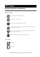
UPS Display Display Symbols and Buttons Navigation symbols Home: Press to go to the UPS Summary screen. Back: Press to go to previous screen. Help: Press to access further details on current screen. Page Up: Press to go to previous screen on same subject (only visible when there are more screens on the same subject). Page Down: Press to go to next screen on same subject (only visible when there are more screens on the same subject). Password logout: Press to log out from password protected screens.
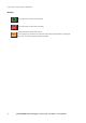
UPS Display: Display Symbols and Buttons Buttons Press this button to switch ON the module. OFF EMO 4 Press this button to switch OFF the module. EMO (Emergency Module OFF) button: Use in emergency situations to shut down the UPS. When the EMO button is engaged on the UPS, AC and DC input and output are disabled.
UPS Summary Screen The LCD touch-screen UPS display is the user interface. It is used to configure the UPS, monitor the system, and change the settings. The display also provides the user with audible and visual alarms. The UPS display is organized hierarchically and the UPS Summary screen is the apex of the hierarchy. To navigate to the UPS Summary screen, touch the house icon in the upper right corner of the screen. The UPS Summary screen gives access to additional screens as shown below.
Input Summary Screens The three Input Summary screens provide input-specific status of voltage, power, current, frequency, etc. Normal Normal UPS Summary 0:00 AM Q2 ~ ~ Q7 Q8 Normal Normal Input Summary Current A 5.40 PM Frequency Hz Total Power kW kVA Voltage V 587 607 495 55.0 522 540 440 54.0 456 472 365 53.0 391 405 330 326 337 275 262 270 220 196 202 165 130 135 110 52.0 51.0 50.0 65 0 67 13 13 13 L1 L2 L3 0 49.0 48.0 47.
Output Summary Screens The three Output Summary screens provide output-specific status of voltage, power, current, frequency, etc. Normal Normal UPS Summary 0:00 AM Q2 ~ ~ Q7 Q8 Normal Normal Output Summary Current A 5.40 PM Frequency Hz Total Power kW kVA Voltage V 587 607 495 55.0 522 540 440 54.0 456 472 365 53.0 391 405 330 326 337 275 262 270 220 196 202 165 130 135 110 65 67 55 The black bars represent real-time data.
Bypass Summary Screens The two Bypass Summary screens provide status of voltage, power, current, frequency, etc. Normal Normal Bypass Summary 0:00 AM Q2 ~ ~ Q7 Q8 Normal Normal Bypass Summary The black bars represent real-time data. Yellow triangles represent the maximum values recorded to date and blue triangles represent the minimum values recorded to date. These values will be reset when the bypass statistics are reset Current A 5.
Battery Summary Screens The three Battery Summary screens provide battery-specific status of voltage, current, run-time remaining, temperature, power, etc. Normal Normal UPS Summary 0:00 AM Q2 ~ ~ Q7 Q8 Normal Normal Battery Summary Current A Voltage V Runtime remaining 495 200 20 5.40 PM 32 37 -160 440 12 m 0 s 385 -340 The black bars represent real-time data.
Operation Screen The Operation screen permits system operation and monitoring, and provides the ability to change display settings (as illustrated in the following menus). Push the Operation/Configuration button to open the Operation screen.
UPS Start-Up Screen From the UPS Start-Up screen, the power flow can be transferred from Manual Bypass to Online Operation. Manual bypass/Off Normal UPS Startup Close Q1 Close breaker Q5 Charge DC Capacitors Close battery breakers Q7 and Q8 Close breaker Q2 Initiate transfer to static bypass Open breaker Q3 Push UPS "ON" button 5.
UPS Shutdown screen Normal Normal UPS Shutdown Initiate transfer to static bypass Close breaker Q3 Open breaker Q5 Push UPS "OFF" button Open breaker Q2 Open battery breakers Q7 and Q8 Open breaker Q1 5.40 PM Initiate transfer Load will be on manual bypass SSW input UPS power down UPS output Isolate UPS from battery UPS input The UPS Shutdown screen shows a list of actions, which need to be completed in order to shut down the UPS.
Online to Static Bypass Screen From the Online to Static Bypass screen, the power flow can be transferred from Online to Static Bypass Operation. Normal Normal Online to Static Bypass Initiate transfer to static bypass 0:00 AM Initiate transfer In static bypass the load is powered directly by utility power. There will be no UPS backup.
Static Bypass to Online Screen From the Static Bypass to Online screen, the power flow can be transferred from Static Bypass to Online Operation.
Network Configuration Screens There are five Network Configuration screens that will be described below: • Network Settings screen • E-mail Settings screen • SNMP Settings screen • Remote Monitoring Service Settings screen • APC ISX Manager Settings screen Network Settings screen All network settings information must be provided before any network functions can be used. Normal Normal Network Configuration 5.39 PM Network Settings Enable network IP Settings Host Name Settings IP address xxx.xxx.xxx.
UPS Display: Network Configuration Screens Host Name Settings. • Host name: The network host name for the system. This uniquely identifies the system on the network. Standard letters (a-z and A-Z), digits (1-9) and hyphen (-) can be used. • Domain name: The DNS network domain that the UPS is on. Standard letters (a-z and A-Z), digits (1-9) and hyphen (-) can be used. SMTP Settings. • From address: The from address to be used when sending e-mails.
UPS Display: Network Configuration Screens • Apply Changes: Select this button after all changes have been made. All entries will appear in red until Apply Changes is pressed. • Send Test E-mail: When this button is pressed, a test E-mail is sent to all configured E-mail recipients. This button can be used to validate the e-mail settings. SNMP Settings screen The UPS can be set to send SNMP traps if UPS alarm conditions occur, and when the conditions return to normal afterwards.
UPS Display: Network Configuration Screens Remote Monitoring Service Settings screen Network settings must be configured before the remote monitoring feature can be used. Note The APC Remote Monitoring Service (RMS) is an APC professional service which securely monitors customer’s power systems and surrounding environment from a remote 24×7 operation center, responding to events according to a pre-defined customer escalation procedure. Visit rms.apc.com to learn more about this service.
UPS Display: Network Configuration Screens APC ISX Manager Settings screen Normal Normal Network Configuration 5.
User Configuration Screens There are five User Configuration screens: • Touch-Screen Settings screen • Password Settings screen • Modbus Settings screen • Regional Settings screen • Battery Test screen Touch-Screen Settings screen The Touch-Screen Settings screen is used to customize the brightness, contrast and backlight of the display.
UPS Display: User Configuration Screens Password Settings screen Some of the UPS Display screens (primarily configuration screens) are protected by a password. On installation the password is set to “apc.” For security reasons, it is recommended to change the password. Normal Normal User Configuration 5.39 PM Password Settings Enter current password xxxx Enter new password xxxxxxxx Re- enter new password xxxxxxxx Apply Changes Page 2 of 5 • Enter current password: Enter the current password.
UPS Display: User Configuration Screens • BMS modbus RTU address: The modbus slave address of the UPS device. • Baud rate • Parity Regional Settings screen Normal Normal User Configuration 5.39 PM Regional Settings Temperature unit xxxx Date format MM_DD_YYYY Apply Changes Page 4 of 5 • Temperature unit: Select Celsius or Fahrenheit. • Date format: Select the preferred date format. • Apply Changes: Press the Apply Changes button when selections have been made.
UPS Display: User Configuration Screens • Battery monitor test: Setting this value to True results in an automatic battery monitor test being performed at regular intervals specified by the Service Engineer. The three options are: – Auto battery test - every (N) week(s). – Auto battery test - on one day of the week. – Auto battery test - at a specific time of the day. • Battery capacity test: Setting this value to True results in the batteries being discharged until a Battery Low Voltage Level is reached.
Event Log Screen The Event Log screen contains a detailed record of the system’s last 1024 events. This includes operation mode changes, system alarms, etc. Normal Alarm: Severe Alarm: Severe Event EventLog Log Refresh E- mail Event Log 242 event(s) downloaded No.
Predictive Maintenance Screens The Predictive Maintenance screens display the stress status and the Expected Remaining Lifetime (ERL) of the critical components of the Symmetra MW UPS system.
UPS Display: Predictive Maintenance Screens Inverter AC Capacitors screen The Inverter AC Capacitor screen displays the actual status and Expected Remaining Lifetime (ERL) of the Inverter AC Capacitors. It is possible to sort the data on the screen by touching either of the column labels. Normal Normal Predictive Maintenance 5.
UPS Display: Predictive Maintenance Screens Top Fans screen The Top Fans screen displays the actual status and Expected Remaining Lifetime (ERL) of the Top Fans. It is possible to sort the data on the screen by touching either of the column labels. Normal Normal Predictive Maintenance 5.
UPS Display: Predictive Maintenance Screens Inverter Fans screen The Inverter Fans screen displays the actual status and Expected Remaining Lifetime (ERL) of the Inverter Fans. It is possible to sort the data on the screen by touching either of the column labels. Normal Normal Predictive Maintenance 5.
UPS Display: Predictive Maintenance Screens Main Static Switch Fans screen The Main Static Switch Fans screen displays the actual status and Expected Remaining Lifetime (ERL) of the Main Static Switch Fans. It is possible to sort the data on the screen by touching either of the column labels. Normal Normal Predictive Maintenance 5.
Operation Modes On-line Operation During on-line operation, the critical load is supported by the inverters. The main inverter controls the output voltage and the delta inverter controls the input current. The delta inverter also provides battery-charging current. While the UPS is running in this mode, a single-line diagram will appear on the screen. The green line indicates the power flow from the utility supply through the UPS to the load.
Battery Operation During battery operation, the load is supported by the inverters. The inverters are supplied by battery power, ensuring uninterrupted support to the load. While the UPS is running in battery operation, a single-line diagram will appear on the screen with a green line indicating the power flow from the batteries through the main inverter to the load for as long as the batteries are energized.
Bypass Operation During bypass operation, the critical load is supplied directly by utility power. A single-line diagram will appear on the screen with an orange line indicating the power flow through the Bypass SSW to the load. CAUTION! Do not open Q2 or Q5 when the UPS is in bypass operation, as this action may result in a load drop or a failure of the UPS to support the load.
Manual Bypass Operation During manual bypass operation, the critical load is supplied directly by utility power, making it possible to isolate the UPS and the Bypass Static Switch for maintenance. Battery power is not available as an alternate power source while the system is running in manual bypass operation. Note A single-line diagram will appear on the screen, with an orange line indicating the power flow from the utility to the load via the Q3 breaker.
System Start-Up from Manual Bypass Operation If the UPS has been operating in manual bypass operation and no power is connected to the UPS, the UPS display will be inactive. To re-start the system from manual bypass and achieve on-line operation, close Q1 in the external maintenance bypass panel. This will power up the internal power supply. Wait for the display to become active and follow the screen-prompted instructions. CAUTION! Follow these instructions carefully.
Operation Modes: System Start-Up from Manual Bypass Operation System Start-Up from Manual Bypass to Online Operation of single mains/utility system - Step-by-Step 1. Close Q1 in the external maintenance bypass panel to power up the internal power supply. Wait for the display to become active. 2. Press Operation/Configuration on the UPS Summary screen on the UPS display. 3. Press Startup on Operation screen. 4. Press “Initiate Charge” on the UPS display to initiate the charging of the UPS DC capacitors. 5.
System Shutdown from Online to Manual Bypass Operation To shut down the UPS (transfer from on-line operation to manual bypass operation), follow the screen-prompted instructions as illustrated. CAUTION! Do not open Q3 when the UPS is in manual bypass operation, as this action may result in a load drop or a failure of the UPS to support the load.
Operation Modes: System Shutdown from Online to Manual Bypass Operation System Shutdown from Online to Manual Bypass Operation of single mains/utility systems - Step-by-Step 1. Press Operation/Configuration on the UPS Summary screen. 2. Select Shutdown on the Operation screen. 3. Press “Initiate Transfer” to initiate the transfer to Static Bypass Operation. 4. Ensure that the green H3 light is illuminated and close the Q3 maintenance bypass breaker. 5. Push OFF button on UPS display to power down the UPS.
Transfer from Online to Static Bypass Operation Follow the below procedure to transfer from Online to Static Bypass Operation: Normal Normal UPS Summary 0:00 AM Q2 ~ ~ Q7 Q8 Select Operation/Configuration on UPS Summary screen Normal Normal Operation Select Online -> Static Bypass on Operation screen Online 5.
Transfer from Static Bypass to Online Operation Follow the below procedure to transfer from Static Bypass to Online Operation: Static Bypass Normal UPS Summary 0:00 AM Q2 ~ ~ Q7 Q8 Select Operation/Configuration on UPS Summary screen Static Bypass Normal Operation Online Startup Transfer from manual bypass to online Shutdown Transfer from online to manual bypass Static Bypass Static Bypass Select Static Bypass -> Online on Operation screen 5.
Alarms/Troubleshooting Alarm Types The color of the top of the screen switches from blue to red when an alarm situation occurs and the alarm symbol is shown at the top of the screen. Alarm button. Pressing the alarm button will take the user to a screen showing all active alarms and how each alarm should be addressed. The 3 different alarm levels are described below. Hitting the alarm symbol or any other display button will automatically silence the alarm. Info Normal 3:51 PM Informational Alarm.
Alarms/Troubleshooting: Alarm Types View active alarms Normal Alarm: Severe Active Alarms Event Log No. Severity 1 2 3 4 Warning Warning Severe Severe 3:51 PM Refresh Event Description Suggested Action Date & Time Mains static switch fan comm.
APC Symmetra MW Remote Display The read-only display screens can be accessed via an Internet Browser by typing the IP address of the Symmetra MW display into the browser’s address field. The remote display feature provides a subset of the Symmetra MW display screens. Configuration of the Symmetra MW or the display through the remote display is not supported. The remote display feature requires Microsoft Internet Explorer 6 SP1 or greater. For best results we recommend that the Sun JVM version 1.4.
APC Symmetra MW Remote Display: Starting web-based remote session • Start the web-based remote session by entering the IP address of the APC Symmetra MW UPS in the web browser address field. After a few seconds, a new window will open and display the below screen: XXX.XXX.XXX.XX • After a few seconds, the UPS display is shown on the screen. • Use the mouse to touch the buttons to see other screens. • Close the window or the web browser to end the remote session.
Warranty Factory Warranty APC warrants that the unit, when properly installed and commissioned by APC or APC authorized service personnel, shall be free from defects in materials and workmanship for a period of (1) year from the date of installation or maximum 18 months after manufacturing.
Life Support Policy As a general policy, American Power Conversion Corporation and its affiliates and subsidiaries worldwide (APC) do not recommend the use of any of its products in life support applications where failure or malfunction of the APC product can be reasonably expected to cause failure of the life support device or to significantly affect its safety or effectiveness. APC does not recommend the use of any of its products in direct patient care.
Appendix A Air Filter Exchange Check air filters at regular intervals (every 3 months under normal working conditions) for accumulated dust on the surface facing the finishing panels. Change all filters at the same time. Pull lower part of top finishing panel free of the UPS. Lift finishing panel free of the dead front panel and remove. Follow this procedure to remove the next finishing panel down, until all panels in one row have been removed.
Appendix A: Air Filter Exchange Note the orientation of the filter. Note Remove air filters and install new filters. Refit finishing panels in reverse order.
APC Worldwide Customer Support Customer support for this or any other APC product is available at no charge in any of the following ways: • Visit the APC Web site to access documents in the APC Knowledge Base and to submit customer support requests. – www.apc.com (Corporate Headquarters) Connect to localized APC Web sites for specific countries, each of which provides customer support information. – www.apc.com/support/ Global support searching APC Knowledge Base and using e-support.