American 12 Operator's Manual and Parts List Active Models: 07001A, 07108A Obsolete Models: 07044C, 07120A, 07049C, 07109A READ THIS BOOK This book has important information for the use and safe operation of this machine. Failure to read this book prior to operating or attempting any service or maintenance procedure to your Clarke American Sanders machine could result in injury to you or to other personnel; damage to the machine or to other property could occur as well.
Contents of this Book Operator Safety Instructions................................................................................ 3 Introduction and Machine Specifications............................................................. 5 230V Electrical Connection Instructions.............................................................. 6 How to Transport the Machine............................................................................. 7 Machine Set-Up.................................................
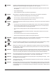
OPERATOR SAFETY INSTRUCTIONS WARNING AVERTISSEMENT ADVERTENCIA DANGER means: WARNING means: CAUTION means: Severe bodily injury or death can occur to you or other personnel if the DANGER statements found on this machine or in this Operator's Manual are ignored or are not adhered to. Read and observe all DANGER statements found in this Operator's Manual and on your machine.
DANGER: DANGER: DANGER: Operating partially assembled sanding equipment could result in injury to the operator or bystander and could cause damage to the equipment or to other property. • Do not operate this equipment unless it it fully assembled and all guards, doors and covers are secured. • Keep all fasteners tight. • Keep all adjustments within manufacturers specifications. Moving parts on this sanding equipment can cause injury to the operator or bystanders.
Operating Controls Introduction and Machine Specifications Operating Controls Motor Starter / Protector Leveling Adjustment Tool Storage Tray Sanding Pres. Adjust MODEL Electrical Requirements Amperage Sound Emisson (Lpm) Vibration Contact Wheel Rate (rpm) Abrasive Rate Fan Flow Rate Abrasive Sheet Size 07108A / 07044C ~208-240V 60 Hz 07109A / 07049C ~220-240V 50 Hz 07120A ~220-240V 50 Hz 07001A ~230V 60 Hz 3Ø 15.7 11.8 11.8 24 83.0 dB(A) 79.4 dB(A) 79.4 dB(A) 83.0 dB(A) <.30 in/s < 2.
230V Electrical Connection Instructions CAUTION: This machine will operate only on AC frequency and on electrical voltage shown on the equipment nameplate. Make sure you have the correct frequency and voltage before connecting the power cord to an outlet. See the example in figure 1. This machine must be connected to an electrical source with an earthing conductor in order to protect the operator from electric shock.
How to Transport the Machine WARNING: The machine is heavy. Remove the motor from the machine before transporting. Get help loading the machine and motor. To transport the machine, follow this procedure: 1. Make sure the power cable is disconnected from the electrical outlet. 2. Disconnect the handle plug connection. See figure 1. 3. Remove the belt cover. 4. Remove the fan belt. Figure 1 5. Loosen the motor bolt. Using the ¾" wrench, turn the motor bolt counterclockwise. See figure 2. 6.
Machine Set-Up To set-up your machine follow this procedure: 1. Familiarize yourself with the machine and read all danger, warning and caution statements. Make sure all operators of this machine have read this Owner's Manual. If they cannot read English, have the manual explained fully before allowing anyone to operate the sander. 2. Locate the power supply. The receptacle should be compatible with the plug. The receptacle must be grounded and must be fused (30 amp) to avoid an electrical hazard. 3.
8. Put the smooth side of the abrasive against the sanding drum. 9. Put one end of the abrasive against the sanding drum slot (1). See figure 3. 10. Turn the drum one revolution. Put the other end of the abrasive in the drum slot (2). See figure 3. 11. Tighten the abrasive. To tighten the abrasive, follow this procedure: 1. The end wrenches are given with the machine. Put a wrench around the nut at each end of the durm (1). See figure 4. Figure 3 2.
How to Operate the Machine DANGER: Sanding/finishing wood floors can create an environment that can be explosive. Cigarette lighters, pilot lights and any other source of ignition can create an explosion when active during a sanding session. All sources of ignition should be extinguished or removed entirely if possible from the work area. DANGER: Work areas that are poorly ventilated can create an explosive environment when certain combustible materials are in the atmosphere, i.e.
To operate the machine follow this procedure: 1. Install the operator's belt as follows: a. Position the operator's belt around waist. b. Cross the straps at the waist. See figure 5. c. Slide the belt loop end over the handle on the control lever side. Adjust the length as needed. d. Wrap the remaining strap around the opposite side of the handle and hold it in place with your hand.
A. First pass forward, right to left. B. First pass reverse, retrace same path. C. Second pass forward, overlap ½ the drum width. D. Second pass reverse, retrace second path forward, etc....for the entire room E. Work the remaining unsanded floor in the same fashion, right to left.
Sanding Cuts and Sandpaper Initial Cut The purpose of the initial cut is to remove old finish and gross imperfections on the floor surface. The sanding equipment should be adjusted to heavy sanding pressure setting and a coarse abrasive should be used. If the surface is severely damaged by deep scratches, pre-existing dwell marks, uneven planks, etc., it may be necessary to sand across or diagonally to the grain to restore evenness to the surface.
Sander Adjustment Procedures DANGER: Electrocution could occur if maintenance and repairs are performed on a unit that is not properly disconnected from the power source. Disconnect the power supply before attempting any maintenance or service. DANGER: Moving parts of this machine can cause serious injury and/or damage. Keep hands, feet and loose clothing away from all moving parts of the sander. Sanding Pressure To adjust the sanding pressure follow this procedure: 1.
Leveling If the sanding drum is out of adjustment, follow this procedure: 1. Remove the belt cover. 2. Loosen the eccentric lock screw. Using the 7/16" wrench, turn the eccentric lock screw (1) counterclockwise. See figure 7. 3. To raise or lower the drum, turn the eccentric (2). See figure 7. 4. Tighten the eccentric lock screw. To tighten the eccentric lock screw, turn the screw clockwise. 5. Install the belt cover.
Routine Maintenance The following items need to be periodically inspected and maintained to keep your sander in good working condition. Wheels Periodically remove the debris from the truck and caster wheels. Debris can cause waves on a sanded surface. Lubricate truck mechanism every 25 hours of use. The machine is equipped with lubrication fittings and are located on shaft supporting mechanism.
Troubleshooting Problem Cause Action Drive belts slip. Insufficient tension. Tension drive belt. (Squeaking or squealing sound) Worn belts. Squealing, growling or grinding Damaged and/or worn bearing. noise coming from machine. Replace belts. Dust pick-up is poor. Dust bag is over 1/3 full. Dust bag is dirty. Dust chute is obstructed.
NOTES Page 18 ® Clarke American Sanders - American 12 Floor Sander Owner's Manual
American 12 Section II Parts Manual (56042622) ® Clarke American Sanders - American 12 Floor Sander Operator's Manual Page 19
HANDLE ASSY [MODELS 07001A, 07108A, 07109A, 07044C, 07049C] 15 27 26 36 39 21 28 23 14 24 42 32 8 1 25 1 10 7 37 43 45 3 17 16 33 8 44 29 41 31 20 35 34 29 18 40 6 12 31 19 44 5 2 11 4 6a 22 38 30 13 6b 9 Page 20 ® Clarke American Sanders - American 12 Floor Sander Owner's Manual
HANDLE ASSY [MODELS 07001A, 07108A, 07109A, 07044C, 07049C] Item Ref. No.
HANDLE ASSY [MODEL 07120A] 20 9 18 7 19 29 13 32 37 15 16 25 17 35 1 1 24 8 5 34 38 30 23 36 3 4 12 21 24 26 10 27 11 21 28 33 2 14 38 31 6 22 Page 22 ® Clarke American Sanders - American 12 Floor Sander Owner's Manual
HANDLE ASSY [MODEL 07120A] Item 1 2 3 4 5 6 7 8 9 10 11 12 13 14 15 16 17 18 19 20 21 22 23 24 25 26 27 28 29 30 31 32 33 34 35 36 37 38 [] ® Ref. No.
14 1 5 6 16 3 15 10 9 17 11 8 4 2 7 FRONT 12 13 MOTOR ASSY [MODEL 07001A] Item 1 2 3 4 5 6 7 8 9 10 11 12 13 14 15 16 17 Ref. No.
3 29 7 11 20 28 1 2 8 14 6 9 26 10 25 21 27 15 13 24 16 23 5 17 4 22 12 19 FRONT 18 MOTOR ASSY [MODELS 07044C, 07108A, 07049C, 07109A] Item 1 2 3 4 5 6 7 8 9 10 11 12 13 14 ® Ref. No.
18 2 20 1 10 21 4 5 9 23 20 6 24 7 13 12 19 14 15 3 25 8 11 17 FRONT 16 22 MOTOR ASSY [MODEL 07120A] Item 1 2 3 4 5 6 7 8 9 10 11 12 13 Ref. No. 962870 10603A 26108C 40676A 40746A 41304A 41306A 46323A 57712A 64460A 67820A 68704A 84220A Qty 1 1 1 1 1 1 1 1 1 1 1 1 1 Page 26 Item 14 15 16 17 18 19 20 21 22 23 24 25 Description Scr 3/8 -16x1 Bt St Allen Inlet Asm Electrical Platform Motor - Black Switchcontrol Floorcrafter Motor 2.
7 10 8 22 19 11 13 12 1 9 17 14 16 3 15 23 19 4 6 21 18 20 2 5 DRUM ASSY Item 1 2 3 4 5 6 7 8 9 10 11 ® Ref. No. 55400A 920280 980644 13500A 22111A 31211A 62608C 64703A 66918A 67314A 67415A Qty 3 1 1 1 1 1 1 1 1 1 1 Description Key 3/16 X 3/4 Dia. Hypro Nut-5/8-18x3/8 Hex Jam Washerflt 5/8 Sae Drum Assembly American 12 Cover Drum American 12 Bumper Assy Cover Drum Shaft Housing-Bearing Shaft Retainerfelt Washerpntdam 8 Scr Shaft-Drum Item 12 13 14 15 16 17 18 19 20 21 22 23 Ref. No.
DUST CONTROL ASSY 16 17 37 13 29 1 12 6 44 21 9 2 30 36 5 1 18 3 10 8 24 32 38 14 45 31 34 35 43 26 ® 42 27 4 15 41 33 11 28 Page 28 7 25 23 22 40 39 19 28 42 20 46 32 Clarke American Sanders - American 12 Floor Sander Owner's Manual
DUST CONTROL ASSY Item 1 2 3 4 5 6 7 8 9 10 11 12 13 14 15 16 17 18 19 20 21 22 23 24 25 26 27 28 29 30 31 32 33 34 35 36 37 38 39 40 41 42 43 44 45 46 ® Ref. No.
BASE ASSY [MODELS 07001A, 07108A, 07109A, 07120A] 27 5 17 18 30 24 13 34 21 16 11 25 23 36 15 38 1 4 22 9 33 29 7 8 12 43 42 40 35 31 32 28 26 39 10 41 37 14 20 2 6 3 19 29 Page 30 33 ® Clarke American Sanders - American 12 Floor Sander Owner's Manual
BASE ASSY [MODELS 07001A, 07108A, 07109A, 07120A] Item 1 2 3 4 5 6 7 8 9 10 11 12 13 14 15 16 17 18 19 20 21 22 23 24 25 26 27 28 29 30 31 32 33 34 35 36 37 38 39 40 41 42 43 ® Ref. No.
BASE ASSY [MODELS 07044C, 07049C] 27 4 16 17 30 25 24 12 33 20 15 10 23 35 14 37 1 3 22 9 32 29 6 8 11 41 39 34 31 7 26 40 36 21 38 19 2 13 5 18 32 29 28 7 Page 32 38 21 ® 8 Clarke American Sanders - American 12 Floor Sander Owner's Manual
BASE ASSY [MODELS 07044C, 07049C] Item 1 2 3 4 5 6 7 8 9 10 11 12 13 14 15 16 17 18 19 20 21 22 23 24 25 26 27 28 29 30 31 32 33 34 35 36 37 38 39 40 41 ® Ref. No.
2 8 3 6 4 7 10 5 9 1 BELT GUARD ASSY [MODELS 07001A, 07108A, 07109A, 07044C, 07049C] Item 1 2 3 4 5 6 7 8 9 10 Ref. No. Qty 21902C 23801A 26000C 51113A 67909A 68001A 86202A 87006A 962892 980657 2 1 1 2 2 1 2 3 4 4 Page 34 Description Clamp - Belt Guard - Black Guard-Belt Pntd Nut - Black Ball 1/2 C.R.
12 2 9 1 13 4 7 6 8 5 10 3 11 BELT GUARD ASSY [MODEL 07120A] Item 1 2 3 4 5 6 7 8 9 10 11 12 13 ® Ref. No. Qty 930087 21097A 21902C 26000C 51113A 67909A 68001A 86202A 87006A 962892 980657 61692A 61693A 7 1 2 1 2 2 1 2 3 4 4 1 1 Description Rivet 1/8dia Usm Ad42bs Guard Belt Am-12 Ce Clamp - Belt Guard - Black Nut - Black Ball 1/2 C.R.
1 1 ACCESSORIES Item 1 [] [] [] [] [] [] [] [] [] [] Ref. No.
Wiring Diagram [models 07044C, 07049C, 07108A and 07109A] Wiring Diagram [model 07120A] ® Clarke American Sanders - American 12 Floor Sander Operator's Manual Page 37
Chatter - Wave Prevention Clarke American Sanders Sanders are designed and manufactured to the most rigid tolerances. However, after a finishing cut it is possible to see “chatter” or “waves”. The best guarantee to remove the chatter is to finish the floor with a rotating horizontal sander, such as Clarke American Sanders’s Sander 16. To minimize chatter when using a belt or drum sander the following steps should be taken: 1) DRUM PAPER...insure the paper is secured in the slot, but not too tight.
Chatter - Wave Prevention (cont) 3) UNEVEN WALKING PACE..... can leave lengthy “waves”. The machine cuts more material during the slower pace. Pay particular attention to a steady, even pace. 4) EXCESSIVE LIGHT CUTS.... may reveal high spots on the paper/contact wheel and cause chatter. Take a heavier cut and increase the pace. 5) DEBRIS.... lodged between the paper and the drum will leave chatter. On a belt sander, debris may be adhered to the drum.
CLARKE AMERICAN SANDERS U.S. AND CANADA LIMITED WARRANTY Amano Pioneer Eclipse, Inc. warrants to the original end user, each new machine, new accessories and genuine replacement parts against defects in material and workmanship under normal use and service. Our obligation under this warranty is limited to repair or replacement of the defective item at our factory or by an Authorized Service Center.