CE7 Pro, SE7 Pro, CE7 Pro+ & SE7 Pro+ Edgers Operator's Manual Manual del operador Manuel de l’utilisateur ACTIVE MODELS: 07170A, 07176A OBSOLETE MODELS: 07180A, 07175A READ THIS BOOK EN LEA ESTE MANUAL ES LISEZ CE MANUEL FR English (2 - 12) Español (14 - 24) Français (26 - 36) This book has important information for the use and safe operation of this machine.
ENGLISH EN CONTENTS OF THIS BOOK Operator Safety Instructions................................................................ 3 Introduction and Machine Specifications............................................. 6 Machine Set-Up................................................................................... 7 How to Operate the Machine............................................................. 11 Maintenance......................................................................................
ENGLISH EN OPERATOR SAFETY INSTRUCTIONS When you see this symbol, it means: Refer to instruction manual/booklet When you see this symbol, it means: Wear eye protection. General Power Tool Safety Warnings WARNING! Read all safety warnings and instructions. Failure to follow warnings and instructions may result in electric shock, fire and or serious injury. Save all warnings and instructions for future use.
ENGLISH EN POWER TOOL USE AND CARE 1. Do not force the power tool. Use the correct power tool for your application. The correct power tool will do the job better and safer at the rate it was designed. 2. Do not use the power tool if the switch does not turn it on and off. Any power tool that cannot be controlled with the switch is dangerous and must be repaired. 3.
ENGLISH EN 14. Regularly clean the power tools air vents. The motor’s fan will draw the dust inside the housing and excessive accumulation may cause electrical hazards. 15. Do not operate the power tool near flammable materials. Sparks could ignite these materials. 16. Do not use excessively oversized sanding disc paper. Follow manufacturer’s recommendations when selecting sanding paper.
ENGLISH EN INTRODUCTION AND MACHINE SPECIFICATIONS The models CE and SE 7 were designed for floor sanding where larger machines are impractical or cannot reach. They are suitable for rough and finish sanding on strip or parquet flooring. They can be used on a wide variety of wood species including pine, oak, or maple. The added reach enables them to be used under obstructions or toe-kick. Either model will accept 7” x 7/8” mounting hole or 7” hook and loop abrasive.
ENGLISH EN MACHINE SET-UP Fig. 1.1 OPERATING HANDLE The operating handle provides control and comfort to the sanding experience (all models). On models 07170A and 07176A, the handles may be set to a greater height depending on preference. Remove the 4 screws securing the handle to the machine. Raise the handle until the holes align then reinstall the 4 screws. Fig. 2.1, 2.2 Abrasive Driver The unit will accept either 7” hook and loop or 7”x7/8” center hole abrasive disc.
ENGLISH EN MACHINE SET-UP Fig. 3.1, 3.2 Dust Management This sanding machine is designed to be operated with a remote vacuum dust collection system or with the included dust bag. D A 2" Hose from vacuum system (not included) 1.5" Hose from vacuum system (not included) Preparing Remote Vacuum Dust Collection Systems To prepare the machine for remote vacuum dust collection systems that have a 2” hose end, follow this procedure: 1. Install 2” hose end (figure 3.
ENGLISH EN MACHINE SET-UP Fig. 4.1 Electrical Connection The unit is equipped with a grounding NEMA L5-15P locking plug (fig 4.1). Connection to an electrical source is made through an extension cord (optional 42300A). Connect the plug on the extension cord to a wall outlet matching one of the two shown (fig. 4.2). Plug the appliance into the matching connector then twist clockwise until the cables are locked.
ENGLISH EN MACHINE SET-UP Fig. 6.1 Sanding Pattern The unit is factory set to sanding pattern 2. 1. To alter the sanding pattern to 1: a.) Loosen the locknuts on A & B. B A b.) Turn stem A counter clockwise and stem B clockwise in 1/4 turn increments until the desired pattern is achieved. c.) Tighten locknuts on A & B. 2. To alter the sanding pattern to 3: a.) Loosen the locknuts on A & B. b.) Turn stem A clockwise and stem B counter clockwise until the desired pattern is achieved. c.
ENGLISH EN How to Operate the Machine Operating Instructions 1. Install the abrasive disc. 2. Connect the dust management system. 3. Connect the extension cord to a wall outlet and then to the machine. 4. Raise the sanding disc from the surface then activate the master control switch. 5. Lower the sanding disc to the surface and begin sanding. Do not press down on the handle while sanding. Doing so will promote objectionable scratches and an uneven finish.
ENGLISH EN MAINTENANCE Drive Belt Replace the drive belt every 1000 hours or on the 3rd set of carbon brushes. Replace lower motor bearing at every drive belt change interval. Replace upper motor bearing every 1500 hours. Motor Bearings Replace lower motor bearing at every drive belt change interval. Replace upper motor bearing every 1500 hours. Abrasive Driver Bearings The bearings should not need replacement for the life of the machine. Carbon Brushes (Figures 8.1 and 8.
ENGLISH Clarke® American Sanders Operator's Manual (EN) - CE7 Pro, SE7 Pro, CE7 Pro+, SE7 Pro+ EN - 13 -
ESPAÑOL ES LEA ESTE MANUAL Este manual contiene información importante acerca del uso y la seguridad de la máquina. Si no lee el manual antes de utilizar su máquina Clarke American Sanders o de intentar realizar los procedimientos de reparación o mantenimiento de la misma, usted o el resto del personal podrían sufrir lesiones; asimismo, podrían producirse dańos a la máquina o a otras propiedades. Antes de utilizar la máquina, es necesario recibir la capacitación adecuada en la operación de la misma.
ESPAÑOL ES INSTRUCCIONES DE SEGURIDAD PARA EL OPERADOR Cuando vea este símbolo, significa: Consultar el libro de instrucciones Cuando vea este símbolo, significa: Usar protección ocular. Advertencias generales de seguridad de la herramienta motorizada ADVERTENCIA: Lea todas las instrucciones y las advertencias de seguridad. Si no respeta todas las instrucciones y advertencias podría sufrir una descarga eléctrica, causar un incendio o sufrir lesiones graves.
ESPAÑOL ES USO Y CUIDADO DE LA HERRAMIENTA MOTORIZADA 1. 2. 3. 4. 5. 6. No fuerce la máquina herramienta. Use la herramienta motorizada correcta para su aplicación. La herramienta motorizada correcta hace un trabajo mejor y más seguro si se usa con la capacidad nominal con que se diseñó. No use la herramienta motorizada si no se enciende y apaga con el interruptor. Una herramienta motorizada que no se puede controlar con el interruptor es peligrosa y debe repararse.
ESPAÑOL ES 14. Limpie periódicamente los orificios de ventilación de la herramienta motorizada. El ventilador del motor atraerá polvo hacia el interior del alojamiento y si se acumula demasiado puede generar riesgos eléctricos. 15. No opere la herramienta motorizada cerca de materiales inflamables. Las chispas podrían encender dichos materiales. 16. No use papel para disco de lijado cuyo tamaño sea excesivamente mayor. Respete las recomendaciones del fabricante cuando elija el papel de lijado.
ESPAÑOL ES INTRODUCCIÓN Y ESPECIFICACIONES DE MÁQUINA Los modelos CE y SE 7 se diseńaron para el lijado de los pisos de aquellos lugares para los que las máquinas de mayor tamańo no resultan prácticas o no tienen alcance. Son adecuados para el lijado de desbaste y acabado de pisos alistonados o de parquet. Pueden usarse para una amplia variedad de tipos de madera entre ellas, pino, roble o arce. Su mayor alcance permite usarlos debajo de obstáculos o terminaciones de bases de muebles (toe-kicks).
ESPAÑOL ES INSTALACIÓN DE LA MÁQUINA Fig. 1.1 EMPUŃADURA DE FUNCIONAMIENTO La empuñadura de funcionamiento permite controlar el lijado y resulta muy cómoda (en todos los modelos). En los modelos 07170A y 07176A, las empuñaduras pueden regularse para lograr una mayor altura según se prefiera. Extraiga los 4 tornillos que sujetan la empuñadura a la máquina. Eleve la empuñadura hasta que los orificios se alineen y luego coloque nuevamente los 4 tornillos. Fig. 2.1, 2.
ESPAÑOL ES INSTALACIÓN DE LA MÁQUINA Fig. 3.1, 3.2 Control de polvo Esta lijadora está diseńada para utilizarse con un sistema colector de polvo remoto mediante vacío o con la bolsa de polvo incluida. Preparación de los sistemas colectores de polvo remotos mediante vacío MANGUERA DE 2" DEL SISTEMA DE ASPIRACIÓN (NO INCLUIDO) D A MANGUERA DE 1.
ESPAÑOL ES INSTALACIÓN DE LA MÁQUINA Fig. 4.1 Conexión eléctrica La unidad está equipada con un enchufe de sujeción NEMA L5-15P de conexión a tierra (fig. 4.1). La conexión al suministro de energía eléctrica se realiza a través de un alargador (opcional 42300A). Conecte el enchufe del alargador a una toma de corriente de la pared igual a una de las dos que se muestran más arriba (fig. 4.2).
ESPAÑOL ES INSTALACIÓN DE LA MÁQUINA Fig. 6.1 Patrón de lijado La unidad está configurada de fábrica con el patrón de lijado 2. 1. Para cambiar el patrón de lijado a 1: a.) Afloje las tuercas de seguridad de A y B. B A b.) Gire el vástago A en sentido contrario a las agujas del reloj y el vástago B en sentido de las agujas del reloj con incrementos de 1/4 de giro hasta lograr el patrón deseado. c.) Ajuste las tuercas de seguridad de A y B. 2. Para cambiar el patrón de lijado a 3: a.
ESPAÑOL ES OPERACIÓN DE LA MÁQUINA Instrucciones de funcionamiento 1. Coloque el disco abrasivo. 2. Conecte el sistema de control de polvo. 3. Conecte el alargador a una toma de corriente de pared y luego a la máquina. 4. Levante el disco de lijado de la superficie y luego active el interruptor de mando principal. 5. Baje el disco de lijado hasta la superficie y comience el lijado. No oprima hacia abajo la empuńadura mientras realiza el lijado.
ESPAÑOL ES MANTENIMIENTO Correa de transmisión Reemplace la correa de transmisión cada 1000 horas o en el tercer juego de escobillas de carbón. Reemplace el cojinete del motor inferior cada vez que se produzca el intervalo de cambio de la correa de transmisión. Reemplace el cojinete del motor inferior cada 1500 horas. Cojinetes de motor Reemplace el cojinete del motor inferior cada vez que se produzca el intervalo de cambio de la correa de transmisión.
ESPAÑOL Clarke® American Sanders Manual del operador (ES) - CE7 Pro, SE7 Pro, CE7 Pro+, SE7 Pro+ ES - 25 -
FRANÇAIS FR LISEZ CE MANUEL Ce Manuel contient des informations importantes concernant l’utilisation et le fonctionnement de cette machine dans des conditions de sécurité optimales. La non-lecture de ce manuel avant d’utiliser ou d’entretenir votre machine Clarke American Sanders risque de provoquer un accident ou d’endommager la machine ou son environnement. Vous devez avoir été formé à l’utilisation de cette machine avant de l’utiliser.
FRANÇAIS FR CONSIGNES DE SECURITE DESTINEES A L’OPERATEUR Ce symbole signifie : reportez-vous au manuel/ notice de l’utilisateur Ce symbole signifie : porter des lunettes de protection. CONSIGNES DE SÉCURITÉ : OUTIL ÉLECTRIQUE AVERTISSEMENT! Veuillez lire attentivement tous les avertissements et instructions de sécurité. Le non-respect des avertissements et des instructions peut entraîner un choc électrique, un incendie ou des blessures graves.
FRANÇAIS FR ENTRETIEN ET PRÉCAUTIONS D’USAGE DE L’OUTIL ÉLECTRIQUE 1. 2. 3. 4. 5. 6. Ne pas forcer sur l’outil électrique. Utiliser l’outil électrique approprié à vos travaux. L’outil électrique adéquat permettra d’effectuer vos travaux dans de bonnes conditions et en toute sécurité. Ne pas utiliser l’outil électrique si l’interrupteur ne peut se mettre consécutivement sur ON et OFF. Un outil électrique qui ne peut être contrôlé par son interrupteur est dangereux et doit être réparé.
FRANÇAIS FR 14. Nettoyer régulièrement les conduits d’air des outils électriques. Le ventilateur du moteur aspire la poussière à l’intérieur du bloc et toute accumulation excessive peut entraîner des défaillances électriques. 15. Ne pas utiliser l’outil électrique à proximité de matériaux inflammables. Les étincelles peuvent enflammer ces matériaux. 16. Ne pas utiliser un disque de ponçage excessivement grand. Suivre les recommandations du fabricant lorsque vous choisissez du papier à poncer.
FRANÇAIS FR INTRODUCTION CARACTÉRISTIQUES TECHNIQUES DES MACHINES Les modèles CE et SE 7 ont été conçus pour poncer les parquets dans les endroits où de plus grosses machines ne sont pas pratiques ou ne peuvent pas accéder. Ils conviennent pour le ponçage brut et de finition sur des parquets traditionnel ou mosaďque. Ils peuvent être utilisés sur une large variété d’espèces de bois y compris le pin, le chêne ou l’érable.
FRANÇAIS FR PRÉPARATION DE L’APPAREIL Fig. 1.1 POIGNÉE DE L’OPÉRATEUR La poignée de l’opérateur permet de contrôler confortablement le ponçage (tous les modèles). Sur les modèles 07170A et 07176A, les poignées peuvent être placées plus haut selon la préférence. Retirez les quatre vis fixant la poignée à la machine. Soulevez la poignée jusqu’à l’alignement des trous et reposez ensuite les 4 vis. Fig. 2.1, 2.
FRANÇAIS FR PRÉPARATION DE L’APPAREIL Fig. 3.1, 3.2 Gestion des poussières Cette ponceuse est conçue pour fonctionner équipée d’un système à distance de collecte des poussières par le vide, ou du sac à poussières fourni. TUYEAU DE 1.
FR FRANÇAIS PRÉPARATION DE L’APPAREIL Fig. 4.1 Connexion électrique L’appareil dispose d’une fiche de verrouillage de mise à la terre NEMA L5-15P (fig 4.1). Une rallonge permet la connexion à une source de courant (facultatif 42300A). Connectez la fiche de la rallonge à une prise murale correspondant à une des deux illustrées (fig. 4.2). Branchez l’appareil dans le connecteur correspondant puis verrouillez les câbles en tournant dans le sens horaire.
FRANÇAIS FR PRÉPARATION DE L’APPAREIL Fig. 6.1 Motif de ponçage L’appareil est réglé en usine sur le motif de ponçage 2. 1. Pour changer la puissance de ponçage à 1 : a.) Desserrez les écrous autobloquants en A et B. B A b.) Tournez la tige A dans le sens antihoraire et la tige B dans le sens horaire par incréments de 1/4 de tour jusqu’à la mise en place du motif. c.) Resserrez les écrous autobloquants en A et B. 2. Pour changer la puissance de ponçage à 3 : a.
FRANÇAIS FR UTILISATION DE L’APPAREIL Directives d’utilisation 1. Installez un disque abrasif. 2. Connectez le dispositif de gestion des poussières. 3. Connectez la rallonge à une prise murale puis à l’appareil. 4. Relevez le disque de ponçage de la surface, puis activez l’interrupteur principal. 5. Abaissez le disque de ponçage sur la surface et commencez à poncer. Ne pas appuyer sur la poignée lors du ponçage. Procéder ainsi entraînera la formation d’éraflures et un fini inégal.
FRANÇAIS FR ENTRETIEN Courroie d’entraînement Remplacez la courroie d’entraînement toutes les 1000 heures ou avec le 3e jeu de balais de charbon. Remplacez le coussinet inférieur du moteur à chaque changement courroie d’entraînement. Remplacez le coussinet supérieur du moteur toutes les 1500 heures Coussinets du moteur Remplacez le coussinet inférieur du moteur à chaque changement courroie d’entraînement.
ENGLISH EN CE7 Pro, SE7 Pro, CE7 Pro+ & SE7 Pro+ Edgers Section II Parts Manual (56042616) Clarke® American Sanders Operator's Manual (EN) - CE7 Pro, SE7 Pro, CE7 Pro+, SE7 Pro+ - 37 -
ENGLISH EN Assembly Drawing 7 63 35 1 61 65 2 3 62 60 9 59 6 58 8 54 55 56 57 5 4 52 53 39 51 37 13 14 15 36 50 47 48 12 38 10 11 17 49 40 20 21 34 35 18 19 23 19 22 46 45 44 43 -38- 41 24 33 25 26 27 32 31 42 30 29 16 64 28 Clarke® American Sanders Operator's Manual (EN) - CE7 Pro, SE7 Pro, CE7 Pro+, SE7 Pro+
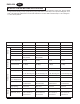
ENGLISH EN ASSEMBLY DRAWING Item Ref. No.
ENGLISH EN Handle Assembly 26 11 25 12 9 8 1 14 10 13 28 18 29 6 24 7 15 16 4 17 18 19 5 22 23 20 30 21 -40- 1 16 3 2 Clarke® American Sanders Operator's Manual (EN) - CE7 Pro, SE7 Pro, CE7 Pro+, SE7 Pro+
ENGLISH EN HANDLE ASSEMBLY Item 1 2 3 4 5 6 7 8 9 10 11 12 13 14 15 16 17 18 19 20 21 22 23 24 25 26 28 29 30 Ref. No. 920056 980621 962727 40943A 11344A 29912A 39871A 61856A 47365A 40947A 29915A 40948A 40265A 40945A 11343A 43401A 80324A 85313C 40946A 85833A 61855A 41079A 962738 29913A 39868A 71468A 71468A 56380216 77094A Qty 4 1 3 1 1 1 1 1 1 1 1 1 1 1 1 4 6 4 1 1 1 2 2 1 1 1 1 1 1 Description Nut, 6-32 E.S.N.A. Nylock (qty of 2 on 07175A & 07180A) Washer, Ext.
ENGLISH EN Motor Housing Assembly 6 5 ORIENT CUT CORNER AS SHOWN. APPLY THIN COAT OF 91600A PRIOR TO INSTALLATION 4 9 7 8 3 2 1 MOTOR HOUSING ASSEMBLY Item 1 2 3 4 5 6 7 8 9 -42- Ref. No.
ENGLISH EN Wiring Diagram Clarke® American Sanders Operator's Manual (EN) - CE7 Pro, SE7 Pro, CE7 Pro+, SE7 Pro+ - 43 -
CLARKE AMERICAN SANDERS U.S. AND CANADA LIMITED WARRANTY Amano Pioneer Eclipse, Inc. warrants to the original end user, each new machine, new accessories and genuine replacement parts against defects in material and workmanship under normal use and service. Our obligation under this warranty is limited to repair or replacement of the defective item at our factory or by an Authorized Service Center.