
Installation Guide


2
7302364-100
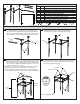
ITEM # QTY. DESCRIPTION
A
B
C
D
E
F
G
H
J
K
1
1
2
1
1
4
4
4
2
4
FRONT LEG SUB-ASSEMBLY (WITHOUT HOLES IN LEGS)
REAR LEG SUB-ASSEMBLY (WITH HOLES IN REAR OF LEGS)
SIDE SUPPORT TUBES
REAR WALL MOUNTING BRACKET
U SHAPED TOP MOUNTING BRACKET
SILICON SINK MOUNTING PADS
M6 x 12.0 HEX ALLEN HEAD MACHINE SCREWS
M6 x 33.1 HEX ALLEN HEAD MACHINE SCREWS
M6 x 6.3 HEX ALLEN HEAD MACHINE SCREWS
RUBBER BUMPERS
8721 CONSOLE TABLE COMPONENTS LIST
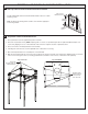
CONSOLE ASSEMBLY
1 2
3 4
Take the front preassembled leg sub-assembly (A) (without
hole drilled behind leg) and insert one of the side support
tubes (C) into the legs protruding mount keeping the support
tubes screw hole facing the oor. Repeat for the opposite side
and screw both side support tubes with included screws (G).
A
B
C
D
E
F G H
KJ
Attach rear preassembled leg sub-assembly (B) (with
hole drilled behind legs) to both side support tubes.
Screw both parts together with supplied screws (G).
Take front preassembled console legs (A) (without holes drilled
behind legs) and the top U shaped mounting bracket (E) and
place bracket over the protruding studs on top of the front and
rear console legs (A&B) as illustrated keeping the open end of
the bracket to the rear of console.
Note: The screw holes on the top bracket where the screws are
placed through are tapered or chamfered on one side of the
bracket to properly t the head of the screw for a at, ush nish.
Use 4 supplied screws (H) to attach bracket to preassembled legs.
Take rear wall mounting bracket (D) (used to mount console
to wall) and attach to rear leg sub-assembly (B) ensuring the
bend in the bracket protrudes slightly towards the wall and
mount using supplied screws (J).
Back of
Console
Front of
Console
Adjustable foot
bumper
Level side-to-side
Level front-to-back
Feet are adjustable
(D)
(B)
(G)
(A)
(B)
(E)
(A)
(C)
(G)
(B)
(H)
(G)