
Installation Guide


2
7302242-100 Rev. A
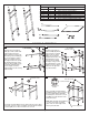
ITEM # QTY. DESCRIPTION
A
B
C
D
E
F
G
1
1
1
1
2
1
8
LEFT SIDE LEG SUB-ASSEMBLY
RIGHT SIDE LEG SUB-ASSEMBLY
BACK TOP SUPPORT TUBE
TOWEL BAR
SHELF SUPPORT TUBE
TEMPERED GLASS SHELF
M4 x 0.7 PHILLIPS HEAD MACHINE SCREW
8719 CONSOLE TABLE COMPONENTS LIST
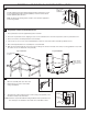
CONSOLE ASSEMBLY
1 2
3 4
Insert the back top support
tube (C) as well as both shelf
support tubes (E) into the
exposed tube housings in the
left side leg sub-assembly (A)
as shown. Align the support
tubes such that the holes in
the support tubes line up with
the threaded housings in the
side leg sub-assembly. Using
3 of the provided machine
screws, tightly secure the
support tubes into the side leg
sub-assembly.
A
B
C
D
E
F
G
3x - included
machine screws
C
A
E
3x - included
machine screws
C
E
B
D
2x - included
machine screws
Adjustable foot
bumper
Level side-to-side
Level front-to-back
Feet are adjustable
Insert the right side leg
sub-assembly (B) into the
exposed ends of support
tubes (C, E) as shown.
Make sure to align the
support tubes holes to the
threaded portion of the
side leg sub-assemblly
housings. Using 3 of the
provided machine screws,
tightly secure the support
tubes into the right side
leg sub-assembly.
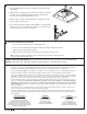
Insert the towel bar (D) into the two exposed holes on the upper
front legs of the the console assembly. Using the final 2 machine
screws, tightly secure the towel rack to the console.
Place assembly into approximate
installation position. Use a level and
the four independently adjustable
foot bumpers to ensure the console
assembly is level both side-to-side
and front-to-back.
Note: Wait until after final installation
of console and sink to assemble
glass shelf onto shelf support and
remove protective film.