
Installation guide


753449-100 Rev. C (2)
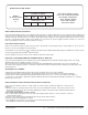
INSTALLATION AND FRAMING INSTRUCTIONS
Locate studs as required. Ensure roughing-in dimensions are proper, plumb and square. Access to Pump/Motor may be made through
the access opening in the apron panel. It is strongly recommended that an additional opening be provided for access to the drain
components.
NOTE: The apron may be used as the primary access opening.
1. As shown in Fig. 1, mark the position of the underside of the deck by tracing a line onto the studs, using a level or other suitable
straight edge.
2. With the top of the stringer touching the traced line, attach the stringer to the studs.
NOTE: Cut a 1/2" deep notch into the stringer to accommadate the air control (see Fig. 4).
3. Install drain components to the whirlpool or bath following the manufacturers instructions. See the roughing-in drawing for suggested
opening size and location dimensions.
4. THIS BATH MUST BE SUPPORTED ALONG ITS ENTIRE BOTTOM. We recommend the use of mortar as bedding material (sand
is not recommended). Apply enough bedding to support the complete bottom of the bath. After the bedding has been poured, and
before it sets, position whirlpool or bath within recess until the rim is leveled against the leveling stringers (see "Typical Recess
Installation") shown below. The rim of the bath MUST NOT support weight. Allow the bedding material to completely harden before
applying weight to the rim or bottom of the bath. Any finish material such as tile or wall board must be self-supporting if it contacts
the deck of the bath.
19-1/4"
(489mm)
FIG. 1
FIG. 3
FIG. 2
TYPICAL RECESS INSTALLATION FRAMING FOR LEFT HAND TUB SHOWN
34" Typ.
(864mm)
19-1/4"
(489mm)
66-3/16"
(1681mm)
30"
(762mm)
3
2"
(813
mm)
TUB W
IDTH
DRAIN END OF TUB
LEVELING
STRINGERS
ALLOW OPEN FRAME ON PUMP/MOTOR
OF WHIRLPOOL FOR PUMP CLEARANCE
(LH SHOWN)
SUGGESTED WHIRLPOOL/BATH
INSTALLATION METHOD
Leveling Stringer
1" x 3" (25 x 76mm) WOOD
Finished Wall
Waterproof Dry Wall
or Cement Board
Sealant
Tu b
Stud
(Wood or Steel)
SECURE THE BATH TO
THE STUDS AS SHOWN
FOR WOOD OR STEEL
STUD CONSTRUCTION.
FIG. 4
LEVELING
STRINGERS
NOTCH FOR
AIR CONTROL
(1/2" DEEP)
42-1/2"
(
1080mm
)
3-1/2"
(
89mm
)