
Installation Instructions
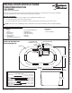


Install Overflow Assembly (H) using supplied Round Gasket (E),
Flange Ring (F) and Brass Overflow Nut (G).
Finger tighten Brass Overflow Nut (G).
Note: Brass Overflow Nut (G) to be tightened further upon
completion of Step 4.
DRAIN Step 2
DRAIN Step 3
DRAIN Step 4
DRAIN Step 5
DRAIN Step 6
BRASS DRAIN BOLT
STRAINER
VERIFY STRAINER
IS LEVEL & FLUSH
WITH TUB SURFACE
TUB FLOOR
GASKET
DRAIN SHOE
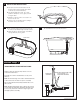
Install Drain Shoe (D) using supplied brass Drain Bolt (A), Strainer (B)
and Gasket (C) as illustrated. Tighten Drain Bolt (A) to secure.
Do not overtighten or Drain Shoe assembly may be damaged.
Note: The top tub lip MUST be level. Verify top and bottom tub
floor sealing surfaces are clean, flat and smooth prior to assembly.
A
B
C
D
Verify Poly-Vinyl Washers (I) are installed under Drain Nuts
(beveled side inward). Tighten Drain Nuts to secure Drain Tee.
Finally, tighten Brass Overflow Nut (J) with an adjustable wrench
to secure Overflow. Do Not Overtighten!
Install Drain Knob over Overflow Shaft (set screw against
flat surface). Then adjust Knob for a 1/16"-1/8" wall gap as
illustrated. Finally, tighten set screw to secure.
CAUTION: Drain Knob wall gap is mandatory to allow
water to escape, preventing overflows.
TUB FLOOR
DRAIN SHOE
MANDATORY DRAIN KNOB WALL GAP
1/16"-1/8"
DRAIN TEE
DRAIN
NUTS
OVERFLOW
ASSEMBLY
VERIFY POLY-VINYL
WASHERS ARE INSTALLED
UNDER DRAIN NUTS
J
BRASS OVERFLOW NUT
I
!
Adjust brass Plunger Bolt and Lock Nut for a 1/2"-5/8" minimum
opening, then tighten Lock Nut against Plumber Shaft to secure
height adjustment.
CAUTION: Plunger Lock Nut must be tightened against plunger
shaft prior to tub use.
!
3
754782-100 Rev. F 11/14
1/2"-5/8"
PLUNGER ASSEMBLY
BRASS PLUNGER
BOLT & LOCK NUT
SILICONE CAULK
REQUIRED
H
E
F
G
TUB WALL
ROUND GASKET
BRASS OVERFLOW NUT
ROUND FLANGE RING
OVERFLOW
ASSEMBLY
3/32" ALLEN WRENCH