
Specification
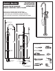
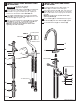

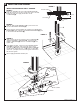


FIGURE 1:
Make sure FLEXIBLE HOT and COLD WATER SUPPLIES
protrude through the 2" (51mm) diameter hole in the floor
enough to make the supply connections to the
“T” ADAPTER (4).
FIGURE 2:
Hold the TUB FILLER ASSEMBLY (1) in place and install
the three MOUNTING SCREWS (2).
Check aligment and level before fully tightening the MOUNTING
SCREWS (2). After tightening the MOUNTING SCREWS (2) push
in the three PLUG BUTTONS (3).
INSTALL TUB FILLER ASSEMBLY
INSTALL WATER SUPPLIES AND “T” ADAPTER
4
FIGURE 1
FIGURE 2
1/2" SUPPLIES
(13mm)
HOT
COLD
1-1/4" (32mm)
M 9 6 5 14 0 R E V. 1. 1
1
2
6
3
FIGURE 3
FIGURE 3:
Apply sealing tape to the threads of the“T” ADAPTER (4)
and the two SUPPLY ADAPTERS (5). Thread the two
SUPPLY ADAPTERS (5) onto the “T” ADAPTER (4) and
tighten fully.
From below the floor, connect the HOT WATER SUPPLY
HOSE (6) (marked with red) to the Hot water supply
from the “T” (4) and the COLD WATER SUPPLY HOSE (7)
to Cold water supply from the “T” (4). Use an adjustable
wrench or 7/8" open end wrench to tighten connections.
Do not over tighten.
Secure piping below floor to floor joist.
4
5
5
1/2"-14 NPT
(13mm)
1/2"-14 NPT
(13mm)
PIPE SUPPORT
RED (HOT)
COLD
SUPPLY
HOT
SUPPLY
7
SEALING TAPE
FINISHED FLOOR
SUB-FLOOR
4
HOT
HOT
HOT