
Installation Sheet


- 2 -
7301450-100 Rev. 2 (3/19)
6
CLOSET
FLANGE
CLOSET
BOLTS
A
3
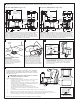
INSTALL CLOSET BOLTS
Install closet bolts in flange channel,
turn 90°, and slide into place 6"
(152mm) apart and parallel to wall.
a. Position toilet squarely to wall and, with a rocking motion, press bowl
down fully on wax ring and flange.
Alternately tighten nuts until toilet is firmly seated on floor.
CAUTION: DO NOT OVERTIGHTEN NUTS OR
BASE MAY BE DAMAGED!
b. Install bolt covers:
1. Make sure that the bolt cover area on the toilet is clean and
dry (see figure). Use a dry piece of cloth or soap and water
if needed.
2. Take plastic bolt cover and peel the brown protective film off
on both ends. The adhesive part is now visible and ready to
be placed on the toilet (see figure).
3. Gently place the bolt cover on the toilet area (see picture) and if
everything is aligned, push bolt cover firmly so it remains in place.
4. If not aligned, you can still take it off and put it back so it is aligned.
5. Repeat Step 3 for second bolt cover which is to be placed on opposite side of the toilet.
6. After 24 hours, the bolt cover adhesive has completely set off and if needed, you can remove/replace
as needed. The dual lock technology is now in place.
c. Smooth off the bead of sealant around base. Remove excess sealant.
!
INSTALL TOILET
5
INSTALL WAX SEAL
Invert toilet on floor (cushion to prevent
damage), and install wax ring evenly
around waste flange (horn), with tapered
end of ring facing toilet. Apply a thin bead
of sealant around toilet base.
POSITION TOILET ON FLANGE
a. Unplug floor waste opening and install toilet on closet
flange so bolts project through mounting holes.
b. Loosely install retainer washers and nuts. Side of
washers marked "THIS SIDE UP" must face up!
4
CLOSET BOLT
NUT
BOLT COVER
Peel both protective films off
and stick bolt cover to toilet.
Back Side
Front Side
BOLT COVER
BOLTS
CLOSET FLANGE
WAX RING
SEALANT
CLOSET
BOLT
NUT
TAPERED
WASHER
FLANGE
OPENING
Model 2847 - TOWN SQUARE 1.28 gpf/ 4.8 Lpf Model 2851A - TOWN SQUARE S 1.28 gpf /4.8 Lpf
ROUGHING-IN DIMENSIONS:
2a
NOTE: Distance from wall to closet flange centerline must be as listed below:
IMPORTANT: Water supply on the wall is required at 3-3/4" or 9" from centerline of the toilet (see rough-in). First suggested position is hidden behind the toilet. The geometry of the toilet gives space for
this installation. The second suggested position is next to the toilet. Between these two positions, the space for the supply between wall and toilet is limited to 3-1/4". In this case, check your supply and
hose dimensions.
29-7/8"
(758 mm)
6-7/8"
(175 mm)
7/8"
(22 mm)
18-1/2"
(470 mm)
3-1/2"
(88 mm)
2-3/4"
(69 mm)
8-1/2"
(217 mm)
14-5/8"
(373 mm)
14-5/8"
(373 mm)
16-1/2"
(419 mm)
15-1/8"
(384 mm)
30-3/4"
(780 mm)
12"
(305 mm)
FINISHED
FLOOR
C/L OF SEAT POST
HOLES 5-1/2"
(140mm) CENTERS
SUPPLY
AS
REQUIRED
(position 1 or
position 2)
6"
(152mm)
5-1/2"
(140mm)
3-3/4"
(95mm)
9"
(229mm)
14"
(356 mm)
18-1/2"
(470 mm)
30-1/4"
(768 mm)
18-7/8"
(480 mm)
4-1/8"
(104 mm)
7-1/2"
(190 mm)
3-1/2"
(88 mm)
2-3/4"
(69 mm)
7/8"
(22 mm)
8-1/2"
(217 mm)
14-5/8"
(373 mm)
14-5/8"
(373 mm)
16-1/2"
(419 mm)
16-1/8"
(416 mm)
30-9/16
(776 mm)
12"
(305 mm)
FINISHED
FLOOR
6"
(152mm)
SUPPLY
AS
REQUIRED
(position 1 or
position 2)
5-1/2"
(140mm)
3-3/4"
(95mm)
9"
(229mm)
14-3/4"
(376 mm)
14"
(357 mm)