
Installation Sheet


Installation Instructions
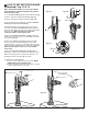
RECOMMENDED TOOLS; Fig. 2
Fig. 2
1.
2.
3.
4.
5.
6.
7.
8.
9.
10.
Teflon Tape
Flat Blade Screwdriver
Adjustable Wrench
Tape Measure
Hacksaw
Tubing Cutter
File
For Sweat Connection; Solder and Torch
2.5mm Hex Wrench
1.5mm Hex Wrench
1
2
3
4
5
6
7910
8
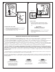
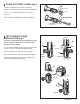
PRIOR TO INSTALLATION
Note: Prior to installing the Selectronic™Flush Valve
the following items must be installed.
1. Water Closet
2. Drain line
3. Water supply line
• Flush all water lines prior to operation (See Step 4). Dirt
and debris can cause flush valve to run continuously.
• With the exception of Supply Stop Inlet, DO NOT use
pipe sealant or plumbing grease on any valve component
or coupling!
• Protect the chrome or special finish on the Flushometer.
DO NOT USE toothed tools on finished surfaces to install
or service these valves. Also see “Care and Cleaning”
section of this manual.
• This product contains mechanical and/or electrical
components that are subject to normal wear. These
components should be checked on a regular basis and
replaced as needed to maintain the valve’s performance.
IMPORTANT:
• All plumbing must be installed in accordance with
applicable codes and regulations.
• Water supply lines must be sized to provide an
adequate volume of water for each fixture.
2
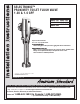
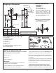
Fig. 1
Roughing-in Dimensions
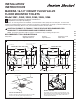
GENERAL DESCRIPTION:
Right or Left Hand Installation
10'
Exposed Flushometer
for 1-1/2" Top Spud Fixtures
SELECTRONIC™
PROXIMITY TOILET
FLUSH VALVE
Exclusive, self cleaning piston-type flush
valve with proximity operation and
manual override. Operates on DC
(battery) power. Recommended
operating pressure 35 to 80 psi. Can
install left or right-handed. Detection
Zone can also be adjusted manually, or
with optional remote control.
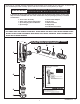
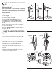
See
(Section 5) for converting Flush
Valve to Left Hand Installation.
M968699 Rev. 1.6
799mm
(31-1/2)
409mm
(16-1/8)
565mm
(22-1/4)
165mm
(6-1/2)
293mm
(11-1/2)
6065.161
6065.121
MODEL X
X
Y
Y
-C-L-
-C-L-
-C-L-
6065.162
6065.122
683mm
(27)
116mm
(4-5/8)
72mm
(2-7/8)
57mm
(2-1/4 MIN.)
DETECTION ZONE
400mm-800mm
(15-3/4 TO 31-1/2)
SUPPLY
DN 25mm
(1” I.P.S.)
15˚
FINISHED WALL
115mm-134mm
(4-1/2 TO 5-1/4)
FOR 1-1/2" TOP
SPUD FIXTURES
MANUAL
OVERRIDE
BUTTON
*CRITICAL
LEVEL
Installation Instructions
*Note: The Critical Line (-C-L-) on Vacuum
Breaker must typically be 6
" (152mm) above
fixture. Consult Codes for details.